
Didactum Knowledge Base · Didactum CAN Devices
8-Port Sensor Expansion Unit
Overview of the device, connections, and technical specifications of the Didactum Expansion Unit for Sensors 8x Analog – the CAN bus expansion module with 8 additional analog sensor ports for all Didactum monitoring systems with a CAN bus port.
What sets the 8-port sensor expansion unit apart
A compact, chainable CAN bus expansion for quickly scaling analog sensing in any Didactum monitoring system.
+8 sensor ports
Each unit instantly expands the system with 8 additional RJ12 ports for analog sensors.
Autosense function
Connected sensors are automatically detected and displayed in the web interface within seconds.
Daisy-chain capable
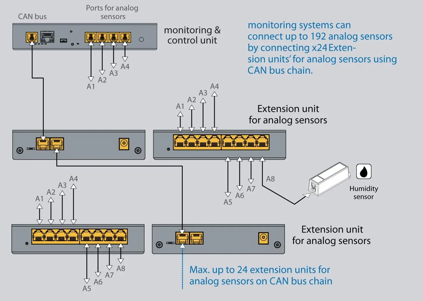
Up to 24 units per CAN bus line – equivalent to up to 192 additional sensor ports.
Long range
Up to 225 m of CAN bus length; sensor cables can be run 50–150 m depending on sensor type.
Flexible mounting
Can be mounted on the wall, on a DIN rail, or in a 19″ rack.
Compatible with all CAN-enabled systems
Can be used with any Didactum monitoring system with a CAN bus port, e.g. 50T, 100T, 300T, 500T, and 550T.
No additional software required
Configuration is done entirely through the Didactum monitoring system's web front end.
Made in EU
Compact, rugged housing for continuous operation, with German support included.
Typical application scenarios
The 8-port sensor expansion box can be deployed in almost any critical environment where the base sensor ports of a Didactum monitoring system are not sufficient.
- Expanding a Didactum monitoring system with additional temperature and humidity sensors
- Connecting additional smoke detectors, water sensors, and door contacts in server rooms
- Building large sensor networks in multi-story buildings via daisy chaining
- Retrofitting existing monitoring installations without replacing the base unit
- Distributed sensor points in production lines and warehouses
- Centralized monitoring of multiple racks over a single CAN bus chain
- Connecting vibration sensors, pressure gauges, and level sensors in Industry 4.0 settings
- Early detection of overheating, humidity, or power outages in critical infrastructure
Connections & controls
All connections, LEDs, and switches of the 8-port sensor expansion unit at a glance.
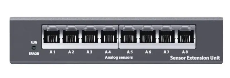
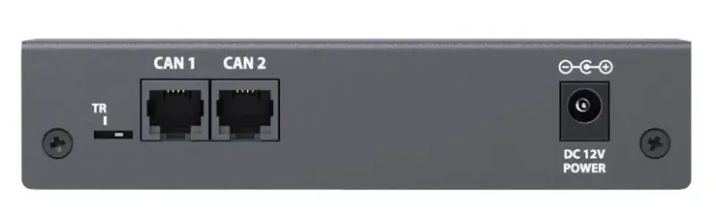
All connections are located on the front of the compact housing: status LEDs and the 8 analog sensor ports A1–A8 on one side, the TR termination switch, the two CAN ports, and the power socket on the other.
Connections 1–2
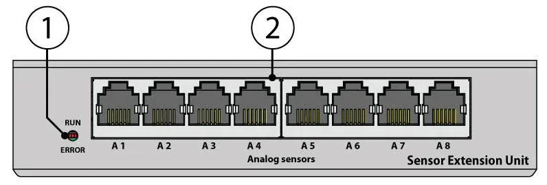
Status LEDs (RUN/ERROR) and the 8 analog sensor inputs A1–A8.
Status LEDs (RUN, ERROR)
"RUN" indicates the connection status to the main module, "ERROR" indicates that the connection to the main module has been lost. If ERROR is lit permanently and RUN is blinking, there is no connection to the monitoring unit. If ERROR is lit permanently and RUN is off, a connection exists but the unit has not yet been configured. If ERROR is off and RUN is lit permanently, the expansion unit is correctly integrated into the monitoring system.
Analog sensors A1…A8
8× RJ11/RJ12 6P4C connectors for analog sensors with automatic detection (Autosense).
Connections 3–5
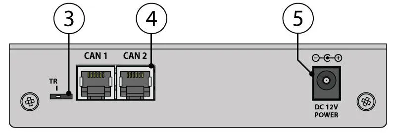
TR termination switch, CAN ports 1 and 2, and the "Power" supply socket.
TR termination switch
If the unit is the last one in the CAN bus chain, or if the chain length exceeds 10 m, the terminator must be set to the "TR" position (to the left). In all other cases, "TR" should always remain switched to the right.
CAN 1 / CAN 2
Two equivalent digital RJ12 connectors for connecting to the main module, to CAN sensors, or to additional CAN expansions on the CAN bus, with automatic detection.
Power (PWR)
Connection for an external 12V DC power supply. Normally a 12V/0.5A power adapter is connected here; with only one expansion unit and a maximum cable length of 10 m to the monitoring system, the external power adapter can be omitted.
Connection diagram
Complete connection diagram of all ports, LEDs, and switches of the expansion unit at a glance.
Scalability in detail
Up to 10–32 CAN devices can be combined on a single CAN bus line – the exact upper limit depends on the total line length, signal quality, and power supply used. In addition to multiple 8-port sensor expansion boxes, digital inputs, relay modules, and temperature, humidity, smoke, door, or motion sensors can also be operated within a single CAN bus segment.
Up to 24 units of the 8-port sensor expansion box can be operated on a single CAN bus line – equivalent to up to 192 additional analog sensor ports on just one monitoring unit. This makes it possible to monitor even large-scale facilities such as multi-story buildings, production lines, or distributed IT infrastructures with just one central Didactum system. When the maximum chain length is reached, the CAN-12V-1A power supply unit is required to ensure additional power on the CAN bus line.
Note: Within a single CAN bus segment (i.e. between two actively terminated endpoints without a CAN power supply unit), the manufacturer recommends no more than 8 CAN units, sensors, and/or other CAN devices. For longer chains with more participants, the use of the CAN-12V-1A power supply unit is required.
Power supply and stability
Normally, an external 12V/0.5A power adapter is connected to the socket labeled "Power". However, if only a single expansion unit is connected and the cable length from the monitoring unit to the expansion box does not exceed 10 m, the unit will also operate without an external power adapter. In all other cases, the use of an external power adapter is recommended.
In larger configurations with many expansion units, power demand increases along the CAN bus chain. This is where the dedicated CAN-12V-1A power supply unit comes in: it is integrated directly into the CAN bus line and reliably supplies power to all downstream devices. Without this additional power supply unit, voltage would drop too much over long chains or with many consumers, which can lead to unstable operation or failures. It is recommended to use the power supply unit approximately every 8–12 units or when the line length exceeds 50 meters.
Flexible mounting options
Depending on the installation location, the expansion unit can be mounted in three different ways. The respective mounting accessories are available separately and are not included in the scope of delivery.
| Accessory | Function | Item number |
|---|---|---|
| Wall bracket | 4× M3 threaded holes on the bottom accept the bracket for wall or surface mounting. | – |
| DIN rail bracket | 2× M4 threaded holes on the bottom accept the bracket for mounting on a DIN rail. | DI15005 |
| Rackmount kit | Mounting one expansion unit in a 19″ server rack, 1 rack unit (1U) high. | DI15001 |
| Rackmount kit (2 units) | Joint mounting of two expansion units in 1 rack unit (1U) in a 19″ rack. | DI15002 |
| CAN-12V-1A power supply unit | Additional power supply on the CAN bus line for long chains or many units. | – |
Setup in a few steps
Commissioning is done without any additional software, directly through the monitoring system's web front end.
Connect the unit's CAN input to the CAN input of the previous CAN unit or the monitoring system using the supplied RJ11/RJ12 cable.
Align the TR bus terminators on the connected CAN units: only set to "ON" (or "TR" position) on the last device in the chain; set to "OFF" on all units in between.
If required, connect an external 12V power supply to the "Power" socket (required for cable lengths over 10 m or multiple units in the chain).
Connect analog sensors to ports A1–A8 – they are automatically detected via Autosense.
In the Didactum monitoring system's web interface, go to "CAN Bus" to access and individually configure the expansion unit and the connected sensors.
Define the desired notification and alarm types (email, SMS via optional GSM modem, SNMP trap, siren, or relay switching).
What's included in the scope of delivery
Please check the scope of delivery for completeness upon receipt and report any missing or damaged parts to your supplier immediately.
- Didactum expansion unit (8x analog)1 piece
- RJ11/RJ12 connecting cable (CAN)1 piece
- Quick start guide1 piece
Wall bracket, DIN rail bracket, rackmount kit, and an additional CAN-12V-1A power supply unit are optional accessories and are not included in the scope of delivery.
Dimensions in detail
Technical data
Function
| Device type | CAN bus expansion device |
|---|---|
| Function | Expands Didactum monitoring systems with 8 additional analog sensor ports per unit |
| Integration | Automatic detection and integration of all connected sensors (Autosense) |
Inputs/outputs & communication
| Analog sensor ports | 8 × RJ11/RJ12 6P4C |
|---|---|
| CAN connectors | 2 × RJ12 |
| Network interface | CAN Open |
| Chain connection | Yes, can be combined with additional CAN sensors and expansions |
System expansion
| Max. units per CAN bus line | up to 24 |
|---|---|
| Max. CAN devices per chain (general) | 10–32, depending on line length, signal quality, and power supply |
| Recommendation per segment without additional power supply | max. 8 CAN units/sensors |
Power supply
| Input voltage | 12V DC |
|---|---|
| Recommended power adapter | 12V / 0.5A (external, at "Power" socket) |
| Operation without external power adapter | Possible with only one unit and max. 10 m cable length to the monitoring system |
| Additional power supply for long chains | CAN-12V-1A, recommended every 8–12 units or from 50 m of line length |
| Max. CAN bus length | 225 m |
| Max. sensor cable length | 50–150 m, depending on sensor type |
Environmental conditions
| Operating temperature | -10 to +80 °C |
|---|
Mechanics & mounting
| Dimensions (W × H × D) | 129 × 28.6 × 56 mm |
|---|---|
| Weight | approx. 0.47 kg |
| Status indicators | Red (error), Green (operation) |
| TR switch | Enable when the unit is the last one in the CAN bus chain |
| Mounting options | Wall bracket, DIN rail bracket, 19″ rackmount kit (each optional, available separately) |
General
| Country of manufacture | EU |
|---|---|
| HS code | 8471 50 000 |
| Compatible systems | All Didactum monitoring systems with a CAN bus port (including 50T, 100T, 300T, 500T, 550T) |
More about the expansion unit
Installation & commissioning
Detailed instructions on connections, LED status, mounting, and setup of the 8-port sensor expansion box.
To the guide →Firmware & updates
Current firmware versions and instructions for updating and restoring.
To the firmware page →Frequently asked questions
What is the Didactum Expansion Unit for Sensors 8x Analog and what is it needed for?
It is a CAN bus expansion that increases the number of analog sensors that can be connected to a Didactum monitoring system by 8 ports per unit. It is needed when the built-in sensor connections of a monitoring system (e.g. 4 or 8 ports) are not sufficient and additional temperature, humidity, smoke, water, or motion sensors need to be connected.
Which Didactum monitoring systems is the expansion unit compatible with?
The expansion unit is compatible with all Didactum monitoring systems that have a CAN bus port, including the 50T, 100T, 300T, 500T, and 550T models.
How many expansion units can I connect to a monitoring system?
Up to 24 expansion units can be operated on a single CAN bus line, which corresponds to up to 192 additional analog sensor ports. In general, up to 10–32 CAN devices can be combined on a single CAN bus line; the exact limit depends on line length, signal quality, and power supply. For a single CAN bus segment without an additional power supply unit, the manufacturer recommends no more than 8 CAN units or sensors.
Do I need an additional power supply for the expansion unit?
If only a single expansion unit is connected and the cable length to the monitoring system is a maximum of 10 m, the unit operates without an external power adapter. In all other cases, as well as with more than 12 CAN devices in the chain, an external 12V/0.5A power adapter or the CAN-12V-1A power supply unit is recommended or required to stabilize the power supply.
What mounting options are available for the expansion unit?
The unit can be mounted on a wall or surface using a wall bracket, placed on a DIN rail using a DIN rail bracket (item DI15005), or installed in a server cabinet using a 19″ rackmount kit (item DI15001, or DI15002 for two units) housing up to two units in 1 rack unit. The respective mounting accessories are available separately.
How do I set the TR termination correctly?
The TR switch must be set to "TR" (to the left) if the unit is the last one in the CAN bus chain or if the chain length exceeds 10 m. For all units in between in the chain, "TR" remains switched to the right (off).
Questions about the 8-port sensor expansion unit?
Our support team in Germany will be happy to advise you free of charge on selection, scaling, installation, and compatibility.