


Didactum Monitoring Systems
Connecting CAN Devices & Sensors
Complete guide for connecting CAN sensors and CAN expansion units to all Didactum monitoring devices.
Connecting CAN Sensors & Devices – Basics
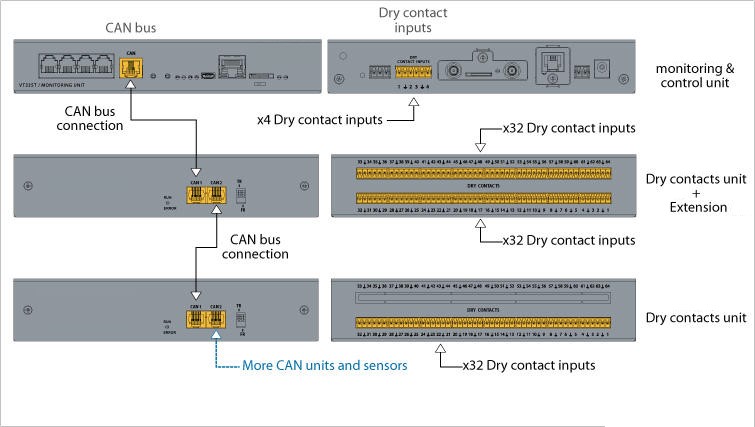
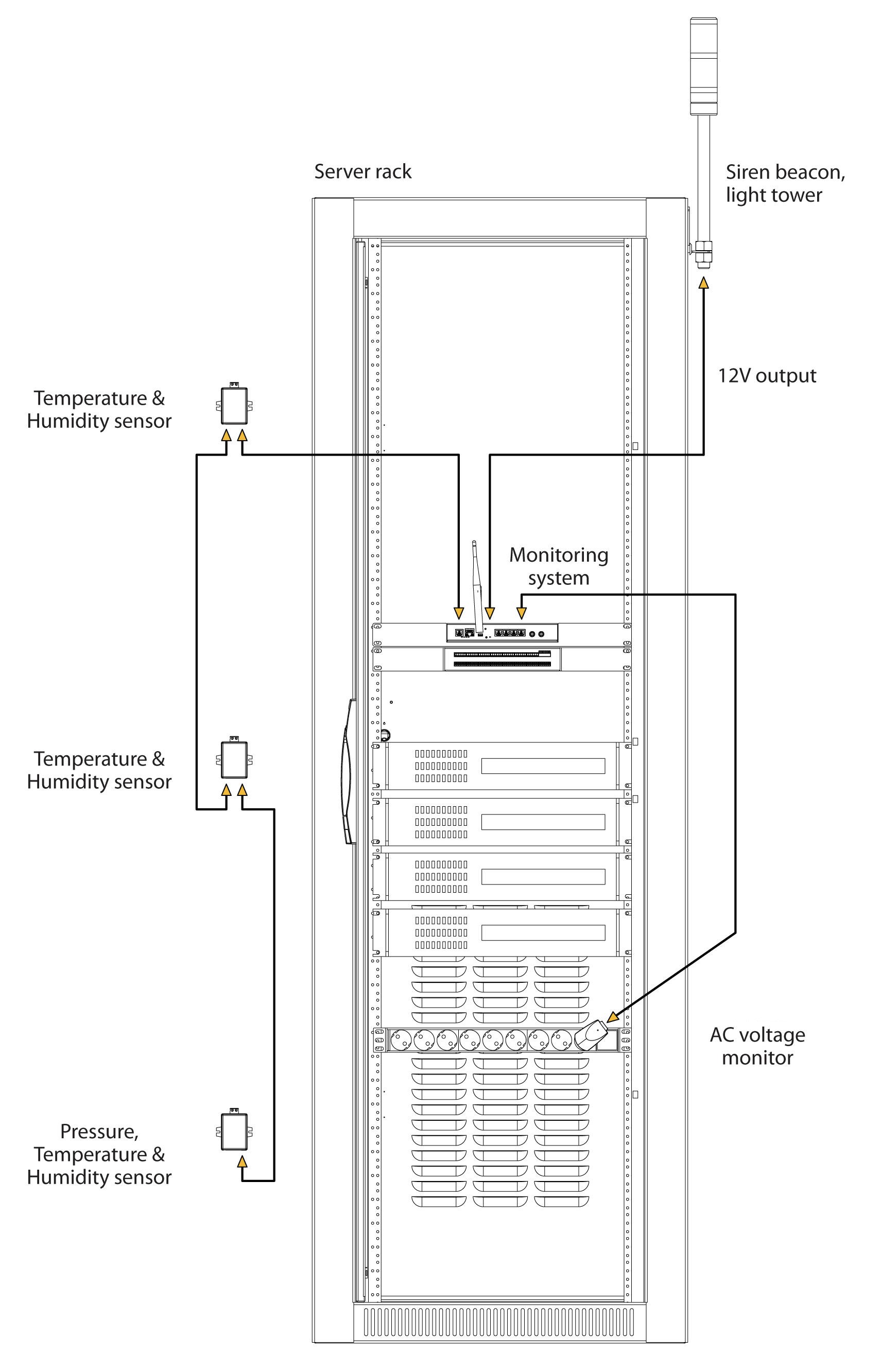
⌄CAN devices and CAN sensors can be connected to all Didactum monitoring systems. You can connect up to 32 CAN units in a single CAN bus chain. The connection is made via the CAN ports of the monitoring device. Additional sensors can then be “daisy-chained” directly to already connected CAN devices.
🔗 Compatible Didactum Monitoring Units
.jpg) 🔍 Enlarge
🔍 Enlarge
 🔍 Enlarge
Connection Steps
- Connect the CAN devices to one of the CAN ports (CAN1 or CAN2) on the Didactum monitoring system using the supplied cable. Additional CAN sensors can be connected directly to the free port of an already connected CAN sensor or CAN unit.
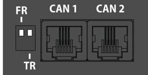
- The TR switch must be set to „ON“ on the last sensor of the respective CAN bus chain. All devices in between must have TR set to „OFF“. The FR switch must always remain OFF.
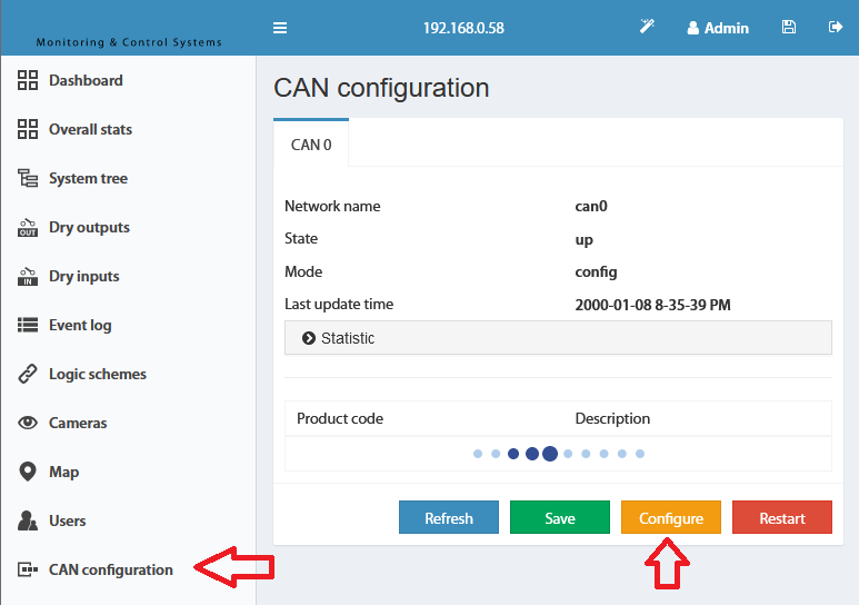
- Open the web interface of the Didactum monitoring system and navigate to the CAN configuration panel. Select CAN1 or CAN2 according to the physically used port.
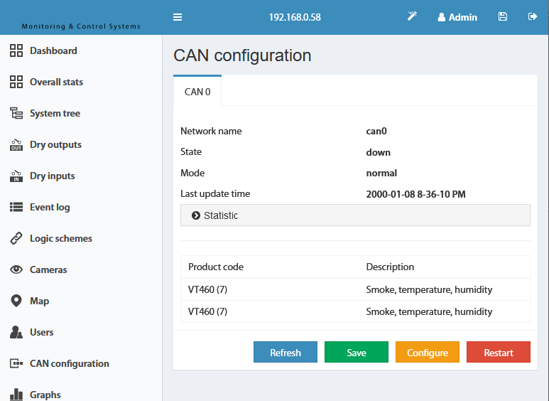
- Click on “Configure” and wait. The system starts the CAN bus polling process and lists all detected devices. Confirm with “Apply” and then “Restart”.
- The green LED “CAN Status” lights up once the integration was successful. New devices appear in the “System Tree” area.
LED Status Display (all CAN sensors)
- Red lights permanently, Green flashes: No connection to the monitoring system (master module).
- Red lights permanently, Green off: Connection to the master module exists, but sensor is not yet configured (not integrated into the monitoring system).
- Red off, Green lights permanently: Sensor is active and integrated into the monitoring system.
- All LEDs off: No power supply or sensor defective.
CAN Cable & Maximum Cable Length
The maximum length of a CAN cable is 225 m, due to the ohmic resistance of cables with RJ12 connectors. The use of 2- or 3-pair cables such as UTP Cat 3/5/6 with 24 AWG and copper core is recommended. Aluminum-copper cables (CCA) have significantly higher resistance – the maximum cable length is considerably reduced as a result.
Systems with two CAN ports
Some Didactum monitoring systems (e.g. Didactum 550T) have two CAN ports. This allows two independent CAN chains to be operated, each of which must be configured separately.
Cable Length Test (Reference Values)
| Model | Description | 50 m | 100 m | 150 m | 200 m |
|---|---|---|---|---|---|
| Didactum Sensor Expansion Unit | Analog Sensor Expansion | – | ✓ | – | – |
| Didactum Dry Contact Expansion Unit | Dry Contact Unit | – | ✓ | Long chain | – |
| CAN Sensor Smoke, Temperature, Humidity | Smoke/Climate Sensor | – | ✓ | – | – |
| CAN Sensor Temperature & Humidity | Climate Sensor (Dual) | – | ✓ | – | – |
Didactum Sensor Expansion Unit
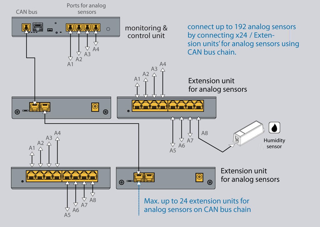
⌄The Didactum Sensor Expansion Unit expands the number of connectable analog sensors on any Didactum monitoring unit. Each expansion unit adds 8 additional analog sensor ports. Multiple units as well as other CAN devices can be daisy-chained together via the CAN bus. All connected sensors are automatically detected and integrated into the system.
 🔍 Enlarge
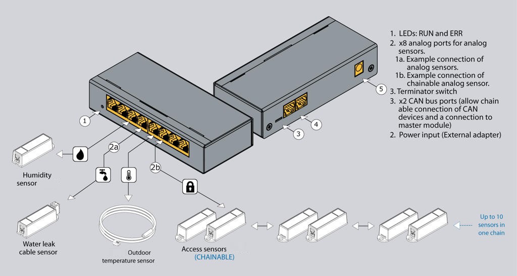
Device Description – Connections & Switches
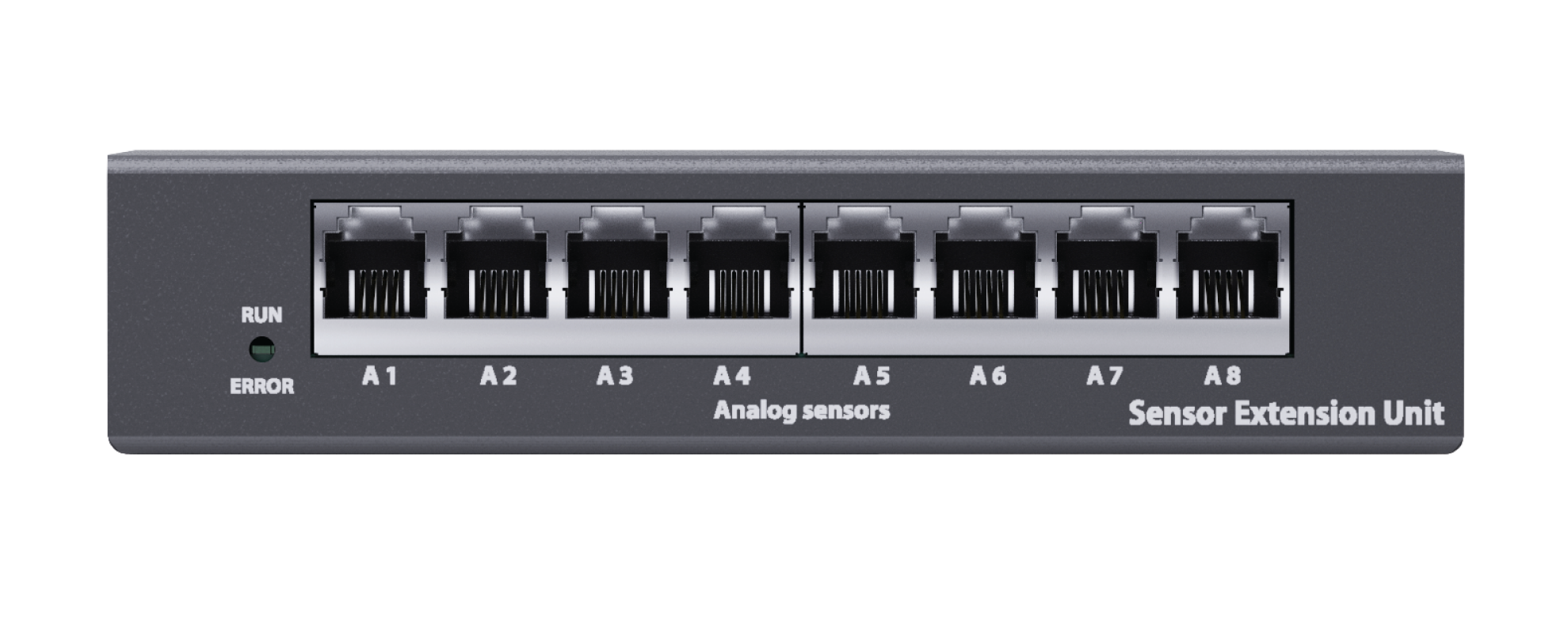
- “RUN” and “ERROR” LEDs: RUN (green) indicates the connection to the main monitoring system. ERROR (red) lights up if the connection to the main module is interrupted.
- A1 … A8: Eight RJ12 analog sensor inputs with automatic detection of the connected sensor type.
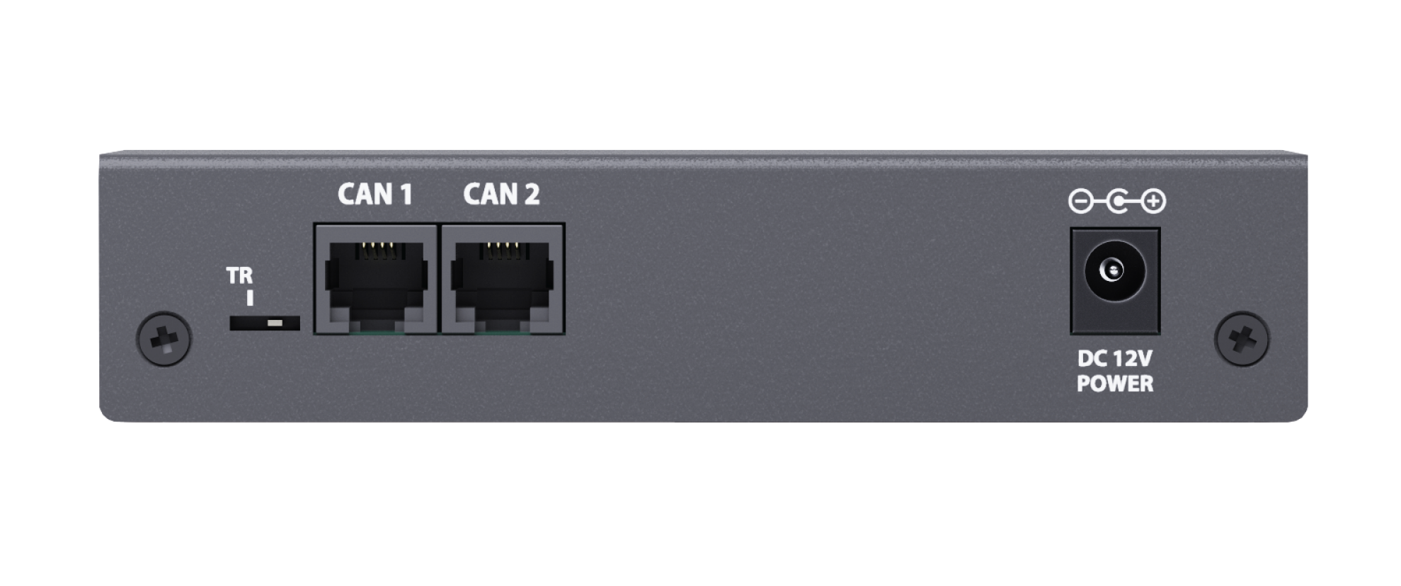
- TR switch: If the expansion unit is the last device in the CAN bus chain or the cable length is more than 10 meters, TR must be set to „TR“ (left). In all other cases TR must be set to the right.
- CAN1 / CAN2: Two equivalent RJ12 digital connections for connecting to the main module, other CAN sensors or CAN expansions with auto-sensing.
- Power supply connection “Power”: For connecting an external 12 V DC power supply.
 🔍 Enlarge
 🔍 Enlarge
Mounting Options
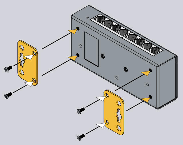 🔍 Enlarge
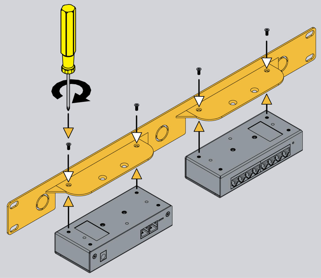 🔍 Enlarge
Installation
- Connect the CAN input of the expansion unit with an RJ11/RJ12 cable to the CAN input of the Didactum monitoring system or the previous CAN device. The red LED lights up.
- Set the TR termination switch on the last device of the CAN chain to ON. All intermediate devices must have TR set to OFF.
- If necessary, connect a 12 V DC power supply to the PWR connection. Note: If only a single expansion unit is connected and the cable is shorter than 10 m, external power supply can be omitted. In all other cases, external power supply is recommended.
- Configure the CAN bus via the Didactum web interface (see section 1).
 🔍 Enlarge
Didactum Dry Contact Expansion Unit
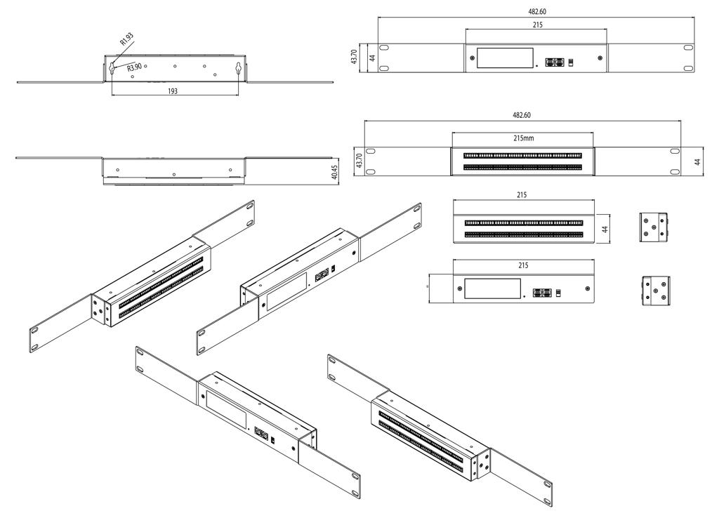
⌄The Didactum Dry Contact Expansion Unit expands the number of dry contact inputs that can be connected to any Didactum monitoring unit. Each unit adds 32 dry contacts and can be daisy-chained via the CAN bus with other CAN sensors and expansions. With the optional expansion board, the number of dry contacts can be increased to 64.
 🔍 Enlarge
Typical Applications for Dry Contacts
- General alarm output
- “System healthy” status message
- Collective fault message
- Door open/closed detection
- Window open/closed
- Air conditioning ON/OFF status
- Power supply control (ON/OFF status of connected devices)
Ordering Options
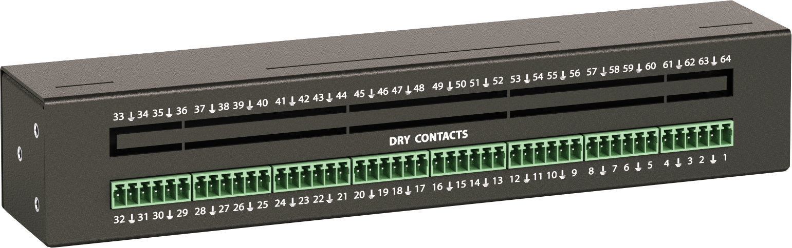 🔍 Enlarge
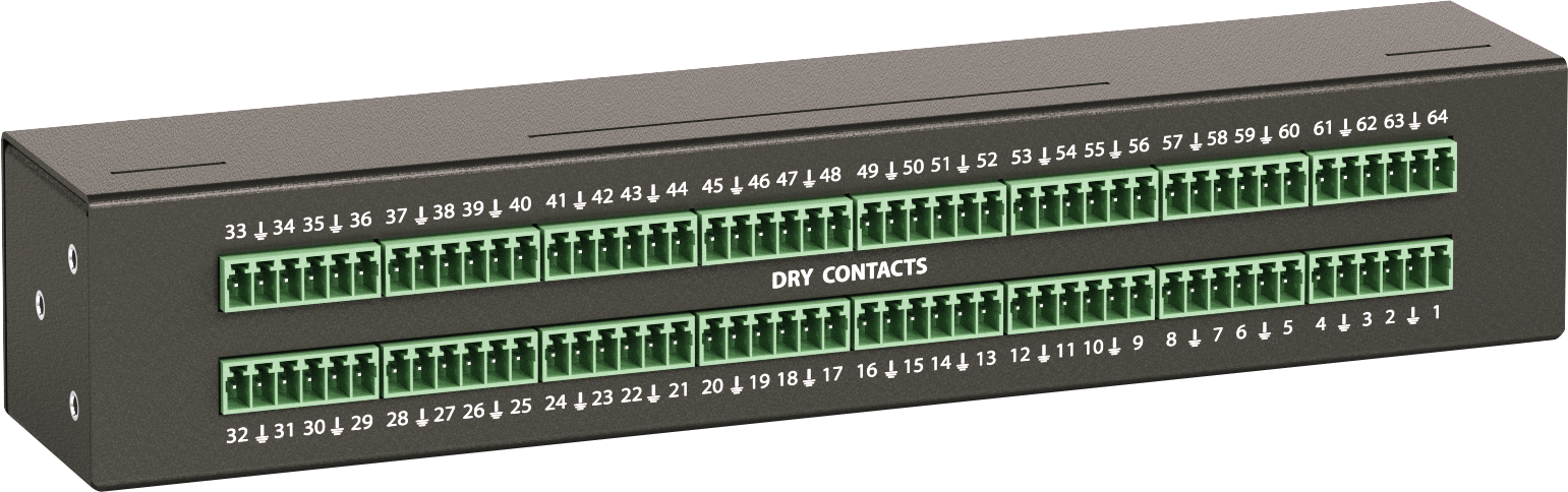 🔍 Enlarge
Device Description – Connections & Switches
- Terminals 1…32: Dry contact input terminals (2-wire).
- Terminals 33…64: Expansion slot – only active when the optional expansion board is installed.
- S/N: Serial number – required for support contact.
- “RUN” and “ERR” LEDs: RUN (green) indicates connection to the main module, ERR (red) indicates an error.
- CAN1 / CAN2: Two equivalent RJ12 digital connections for the CAN bus.
- TR switch: Must be set to „ON“ on the last sensor in the CAN chain. For long chains (more than 10 m) and the last device set to „ON“.
TR Switch Positions
🔍 Enlarge
🔍 Enlarge
 🔍 Enlarge
Didactum CAN Sensor Temperature, Humidity & Pressure
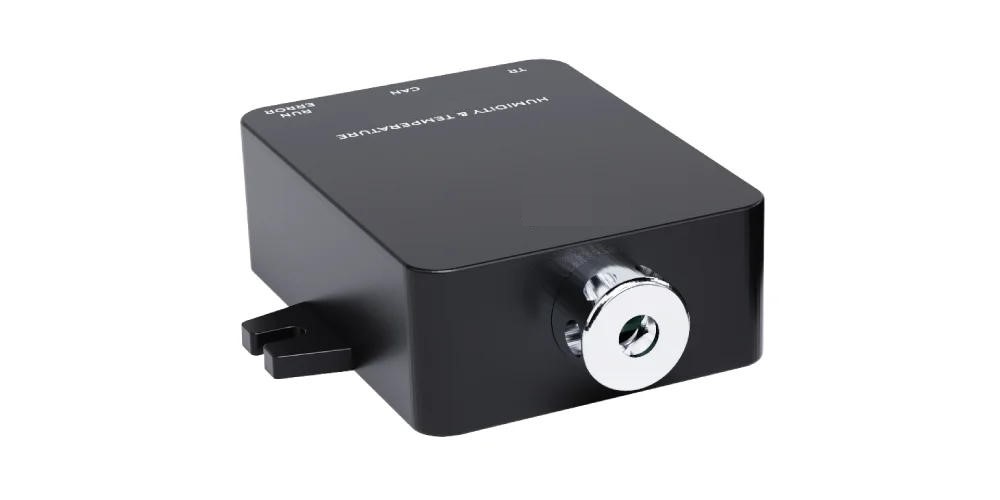
⌄The Didactum CAN Sensor Temperature, Humidity & Pressure is a versatile digital sensor that measures all three environmental parameters with high precision. In the Didactum web interface, each measured value (pressure, humidity, temperature) is displayed as a separate element, allowing individual threshold values and alarm actions to be configured. In addition, the sensor calculates the dew point, which makes monitoring condensation-prone areas easier.
 🔍 Enlarge
 🔍 Enlarge
Applications
- Data Centers & Server Rooms: Precise monitoring of temperature, humidity and air pressure to protect against overheating, condensation and overpressure.
- Clean Rooms: Maintaining optimal conditions for sensitive manufacturing processes in the pharmaceutical or semiconductor industry.
Device Description – Connections & Switches
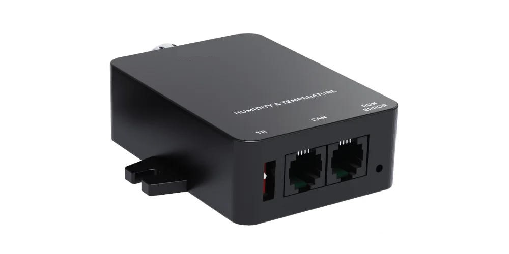
- “RUN” (green) and “ERROR/ERR” (red) LEDs: RUN lights up permanently with a correct connection; ERROR/ERR indicates an error or connection loss.
- Pressure/Humidity/Temperature Sensor: The sensor element is located on the outside of the housing for better measurement accuracy.
- TR switch: Set to „ON“ (down) when the sensor is the last device in the CAN chain. Otherwise set to „OFF“ (up).
- CAN Ports: Two equivalent RJ11 6P4C connectors for the CAN bus connection, with auto-sensing.
 🔍 Enlarge
 🔍 Enlarge
 🔍 Enlarge
TR Switch Examples
Example 2 (intermediate device): 5 sensors in chain, this one is not the last → TR set to „OFF“ (up).
Example 3 (last device): 5 sensors in chain, this one is the last → TR set to „ON“ (down).
Didactum CAN Sensor Smoke, Temperature & Humidity
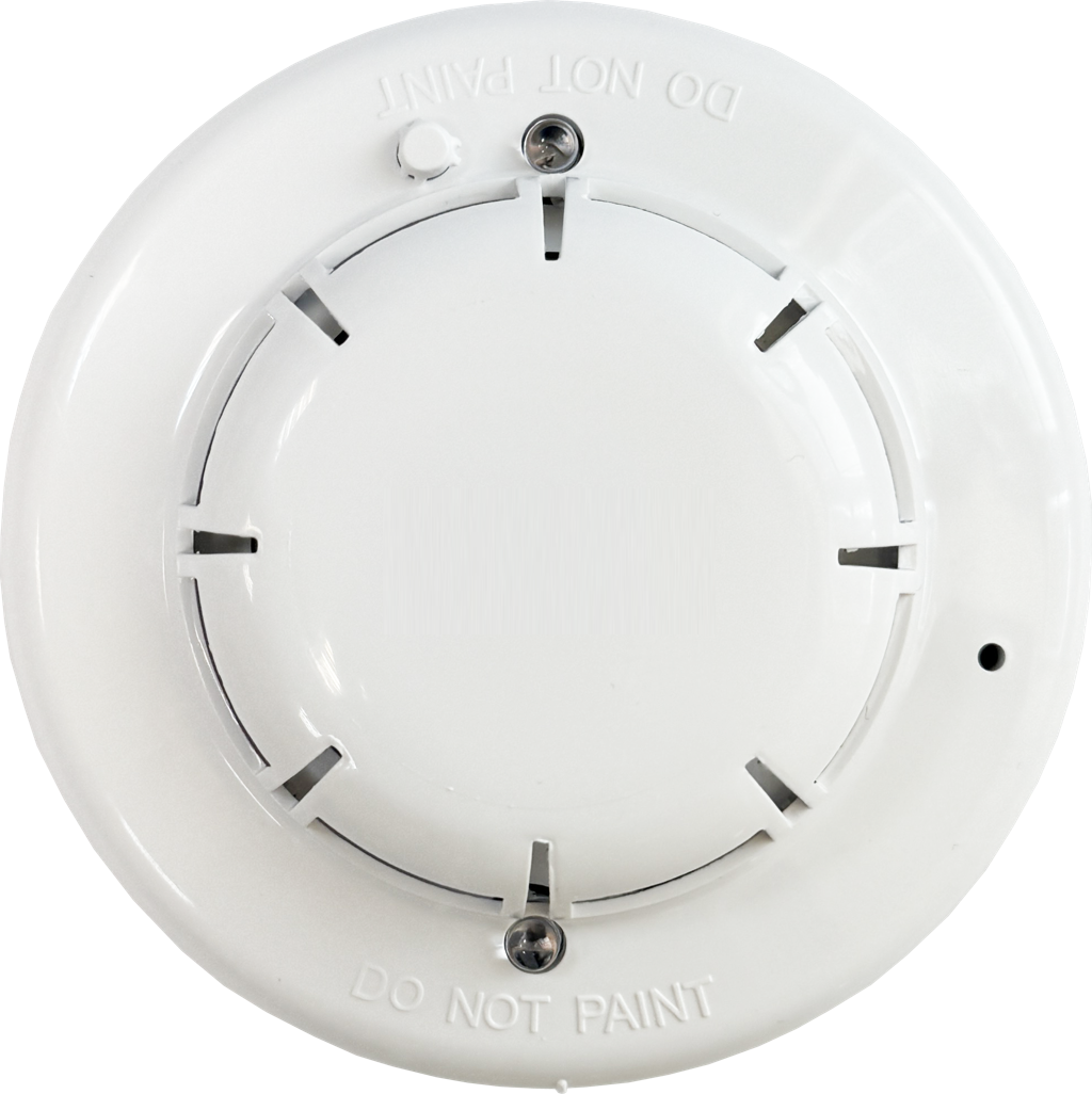
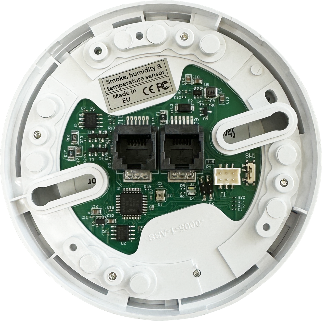
⌄The Didactum CAN Sensor Smoke, Temperature & Humidity combines smoke, temperature and humidity monitoring in a single device. Thanks to its high smoke sensitivity, even low smoke concentrations are detected, making it an essential tool for early fire detection in critical environments. Each environmental parameter is displayed as a separate element in the web interface, allowing individual threshold values and alarm actions to be configured.
 🔍 Enlarge
 🔍 Enlarge
Applications
- Fire Protection Monitoring: Integration into fire alarm systems for real-time monitoring of smoke levels in buildings, warehouses and production facilities.
- Data Centers & Server Rooms: Early detection of smoke and heat to protect critical IT infrastructure and minimize downtime.
LED Status Indicators
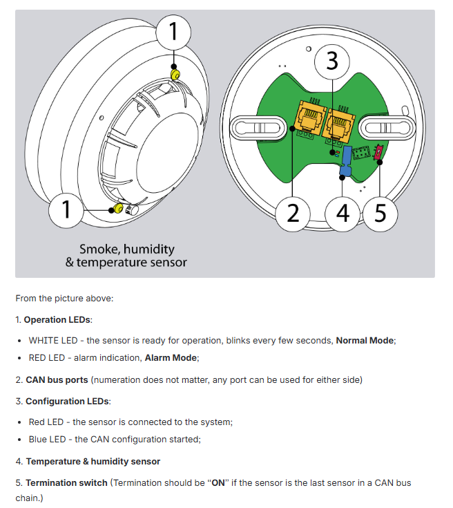
- White LED flashes (every few seconds): Sensor ready for operation – Normal operation.
- Red LED lights permanently: Smoke alarm – Alarm mode.
- Red configuration LED: Sensor is connected to the system.
- Blue configuration LED: CAN configuration has been started.
 🔍 Enlarge
Mounting Instructions
 🔍 Enlarge
 🔍 Enlarge
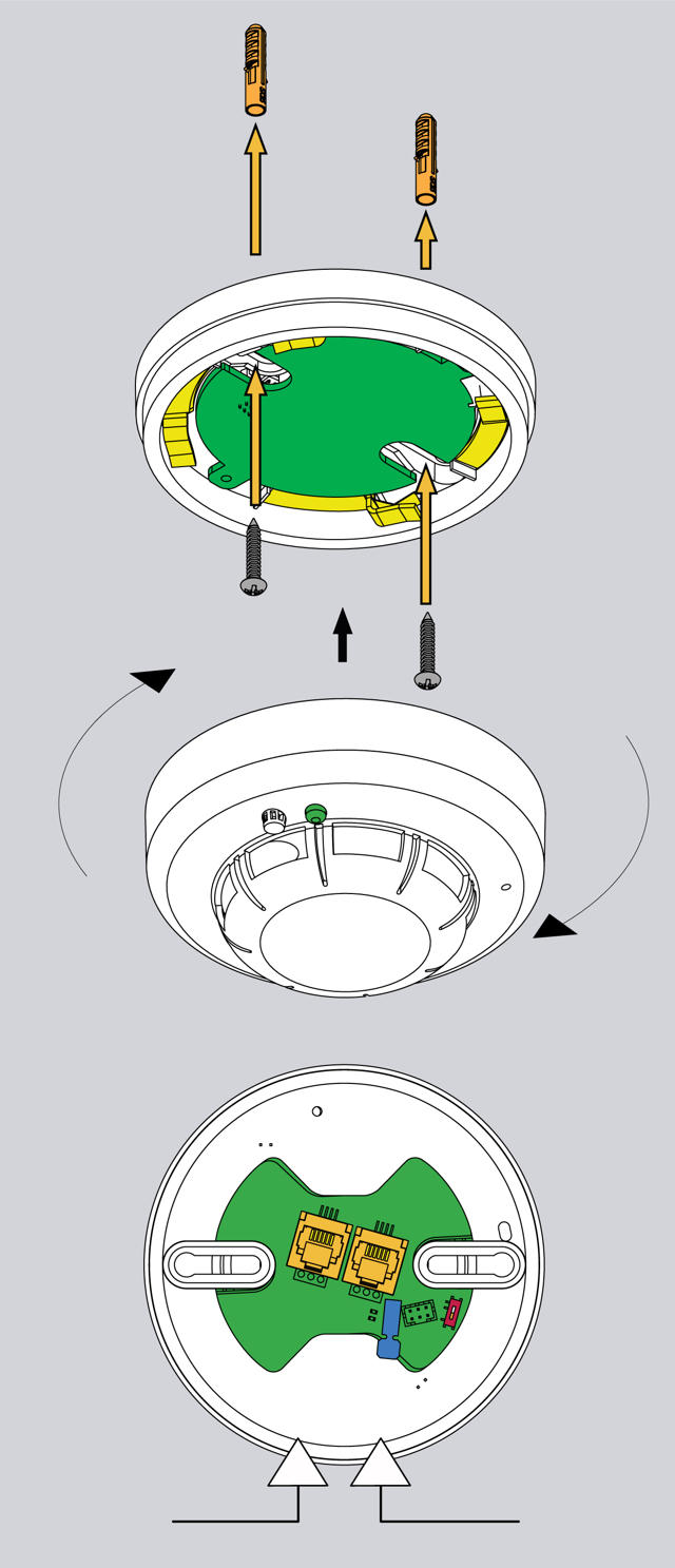
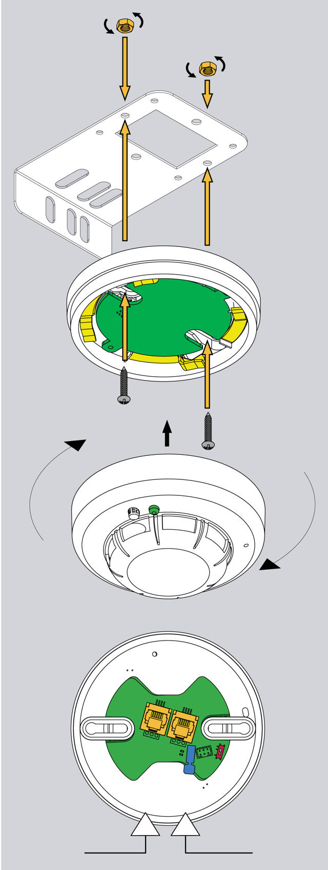
- Remove the smoke detector head from the base.
- Attach the base to the mounting plate using the supplied M4 × 10 screws.
- Place the smoke detector head back on the base and lock it by turning.
- Attach the mounting plate to the enclosure frame or ceiling using the supplied 4.8 × 19 screws.
- Remove the red protective cap from the sensor.
Connecting the Sensor
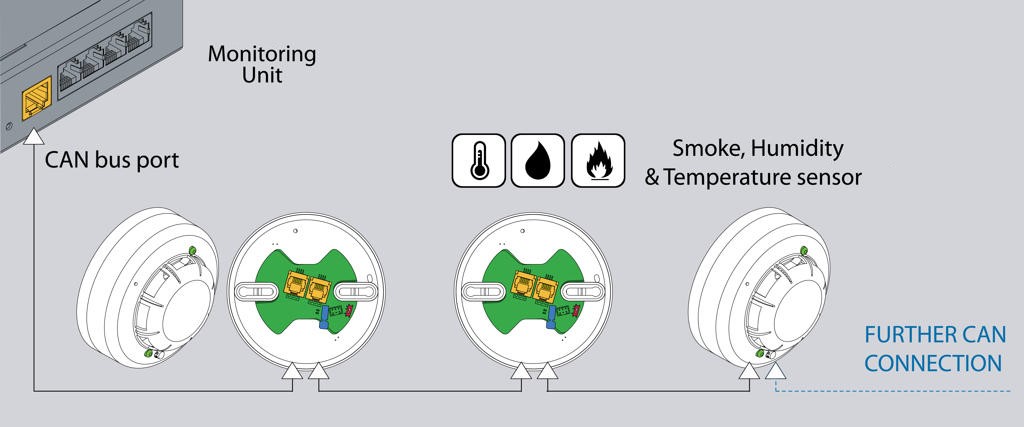
Connect one end of the RJ11/RJ12 cable to the CAN port of the Didactum monitoring system and the other end to one of the CAN inputs of the smoke sensor. Up to 10 sensors can be connected in a chain to one CAN port. For each additional sensor, plug a new RJ11 cable into the free input of the already connected sensor.
 🔍 Enlarge
Configuring the Sensor
 🔍 Enlarge
 🔍 Enlarge
Didactum CAN Sensor Temperature & Humidity
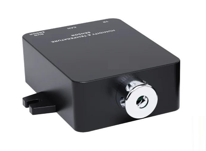
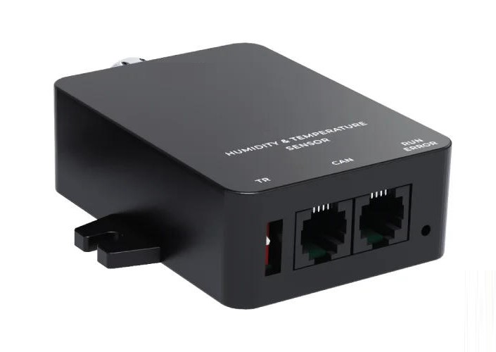
⌄The Didactum CAN Sensor Temperature & Humidity is a high-quality, precise sensor for reliable environmental monitoring. Multiple units can be connected in a chain via the CAN bus to measure temperature and humidity at different points in the room or server rack. In the web interface, the sensor also automatically calculates the dew point from temperature and humidity.
 🔍 Enlarge
 🔍 Enlarge
Applications
- Data Center Monitoring: Monitoring of critical environmental factors such as temperature and humidity in data centers to prevent failures.
- Industrial Facilities: Monitoring of environmental conditions in production sites.
- Warehouses & Storage Halls: Protection of goods against moisture damage and mold growth.
- Pharmaceutical Storage Rooms: Precise climate control for medications and vaccines.
- Food Processing Plants: Monitoring of temperature and humidity to comply with food safety standards.
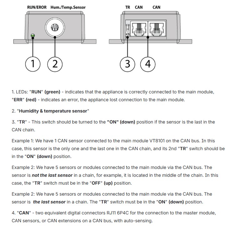
Device Description – Connections & Switches
- “RUN” (green) and “ERR” (red) LEDs: RUN lights up permanently when correctly integrated; ERR indicates an error or connection loss.
- Temperature & Humidity Sensor: The sensor element for climate measurement.
- TR switch: Set to „ON“ (down) when the sensor is the last device in the CAN chain.
- CAN Ports: Two equivalent RJ11 6P4C connectors with auto-sensing.
 🔍 Enlarge
 🔍 Enlarge
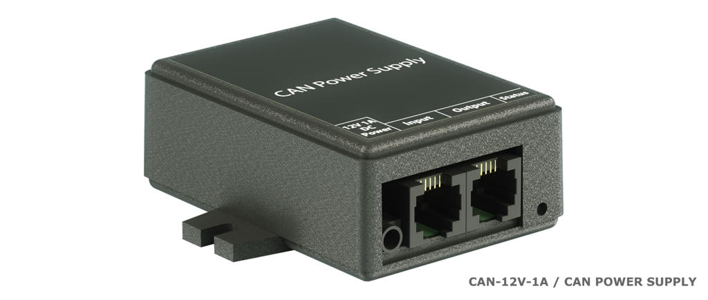
Didactum Power Supply for CAN Devices 12V/1A
⌄The Didactum Power Supply for CAN Devices 12V/1A is required when more than 12 CAN devices are to be operated in a bus chain. It supplies each additional group of up to 12 CAN devices (sensors and expansion units) with sufficient power.
 🔍 Enlarge
Device Description – Connections
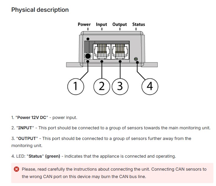
- “Power 12V DC” connection: Connect the external 12 V DC power adapter here (hollow plug ⌀ 3.4/1.35 mm).
- “INPUT” port: This port must be connected to the sensor group that lies toward the monitoring system (Group 1 – closer to the main device).
- “OUTPUT” port: This port is connected to the sensor group that lies further away from the monitoring system (Group 2 – behind the power supply).
- “Status” LED (green): Lights up when the device is connected and functioning correctly.
 🔍 Enlarge
Step-by-Step Connection
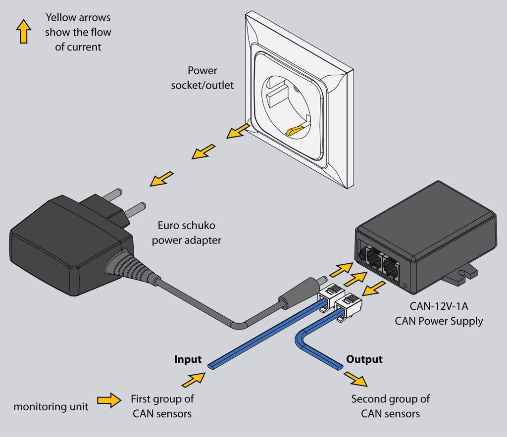
Step 1 – Connect Sensor Group 2 to OUTPUT
 🔍 Enlarge
- Connect the power supply to the mains socket using a Euro plug adapter. The status LED lights up green.
- Connect all additional sensors (Group 2) to the OUTPUT port of the power supply. Group 2 may contain a maximum of 15 sensors in a chain.
- Check whether all sensors in Group 2 light up. If some do not respond, reduce the number of connected sensors.
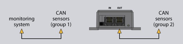
Step 2 – Connect Sensor Group 1 to INPUT & Set TR Switches
 🔍 Enlarge
- Connect the last sensor of Group 1 (closer to the Didactum monitoring system) to the INPUT port of the power supply.
- Set the TR switch of the last sensor in Group 1 to OFF (since the chain continues through the power supply).
- Set the TR switch of the last sensor in Group 2 to ON.
- Configure the CAN bus in the Didactum web interface (see section 1).
 🔍 Enlarge
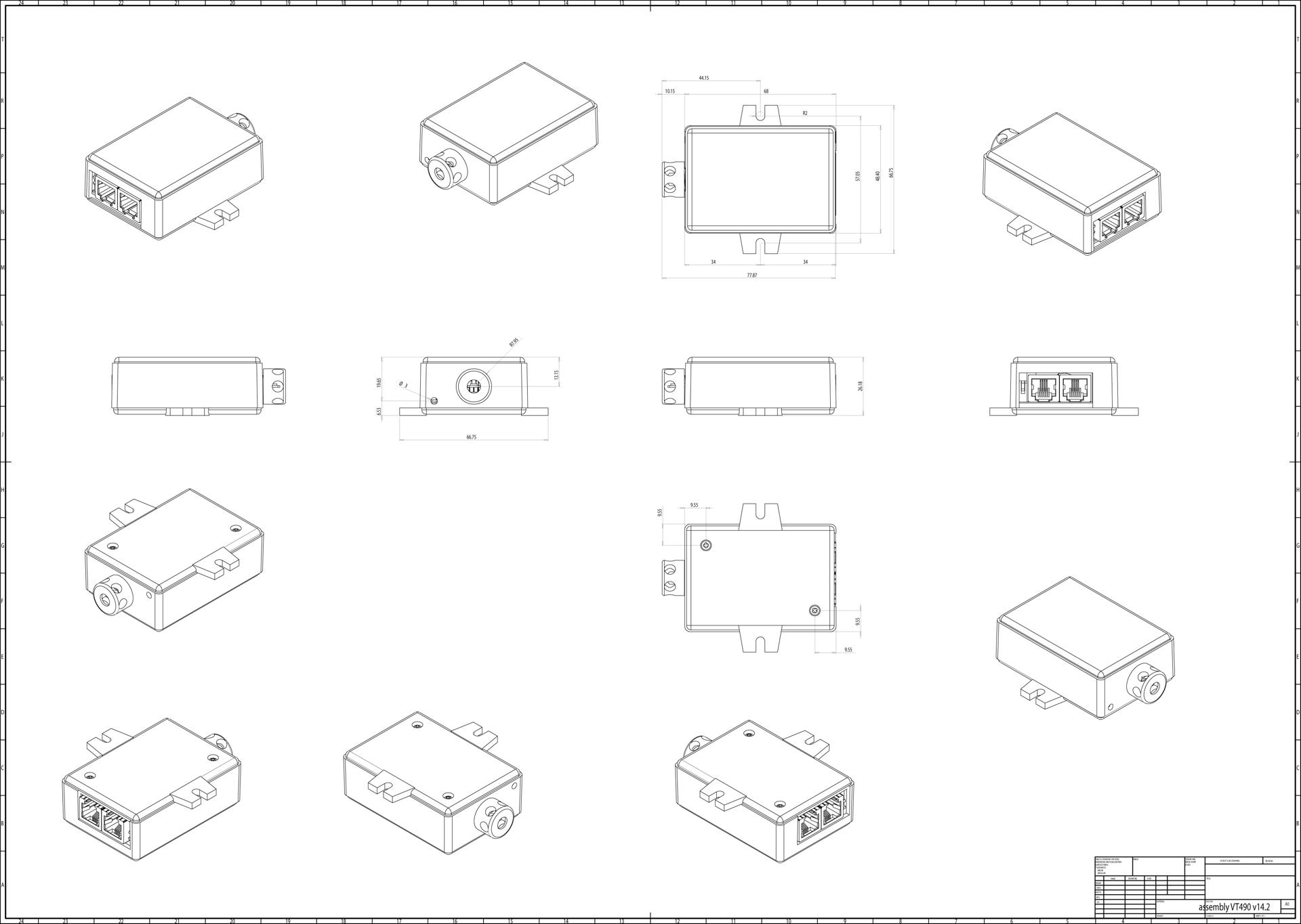
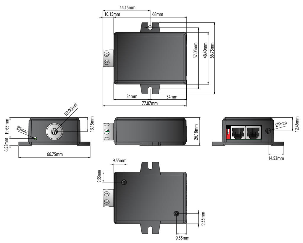
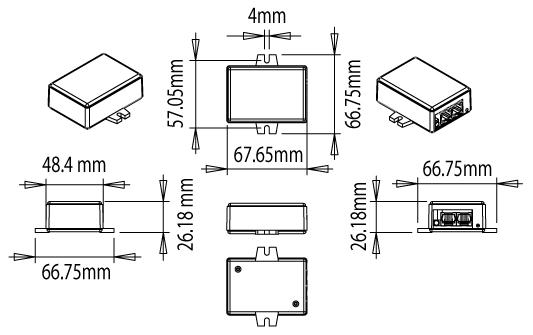
Dimensional Drawing
 🔍 Enlarge