


Didactum Knowledge Base · Didactum Devices
Monitoring System 100T
Overview of the device, connections, and technical specifications of the Didactum Monitoring System 100T – the powerful monitoring solution with Gigabit Ethernet, CAN bus expansion, and optional LTE modem for server rooms, data centers, and industrial facilities.


What sets the 100T apart
A powerful, scalable solution for the holistic monitoring of medium and larger IT environments.
Holistic monitoring
Server room, building, and IT monitoring in a single compact unit.
Up to 100 sensors
4 analog ports directly on the device, expandable via CAN bus to up to 32 devices.
Real-time alerting
Via email, SMS, SNMP trap, syslog, or a connected siren.
Web-based
Compatible with Zabbix, PRTG, Nagios, and Check_MK, with no additional software required.
I/O control
Automated control of UPS, HVAC, access, doors, and lighting.
Scalable
Up to 700 elements – notifications, triggers, timers, logic schemes.
Building security
Door contacts, motion detectors, and glass-break sensors can be integrated.
LTE & expansion slot
Optional LTE modem plus upgradable Modbus/RTU or OSDPv2 expansion.
Made in EU
Metal housing, German support included, regular firmware updates.
Typical use cases
- Temperature and humidity monitoring in server and IT rooms, telecom facilities, and network cabinets
- Leak detection under raised floors or in air conditioning and cooling systems
- Monitoring of UPS systems, power supply, and backup generators
- Security monitoring of doors, windows, and server cabinets
- Vibration monitoring to protect against sabotage or unauthorized access
- Remote monitoring of branch offices and remote sites, optionally via LTE
- Monitoring of production, manufacturing, and warehouse facilities as well as cold storage and freezer rooms
- Video surveillance via USB or IP camera in combination with sensor alarms
Connections & Controls
All ports, buttons, and LEDs on the front and rear panel of the 100T, plus the complete wiring diagram at a glance.
All sensor and network connections are deliberately distributed across two sides of the metal housing: at the front are the connections for day-to-day operation – the four analog sensor ports A1–A4, the CAN port, USB, LAN, the SD card slot, the DIP switch for system recovery, and the status LEDs. At the rear sit the chassis ground, the integrated temperature sensor, the relay outputs, the dry contact inputs, the modem and expansion slot, and the power supply including the backup input.
Front view
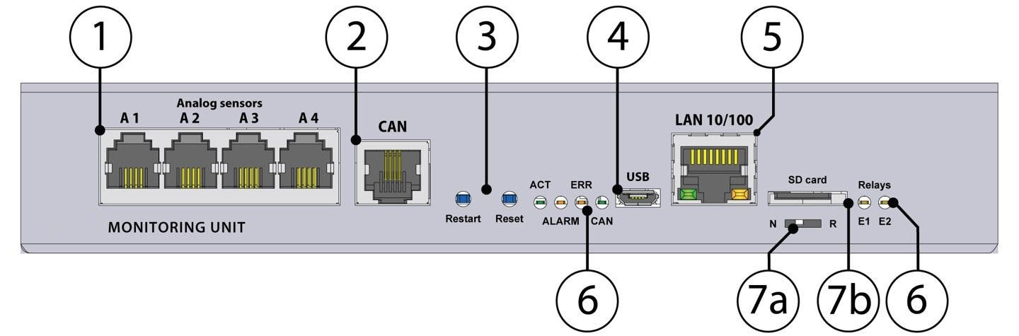
Front view: analog sensor ports A1–A4, CAN, restart/reset, USB, LAN, status LEDs, DIP switch, SD card.
Analog sensors A1–A4
4× RJ12 6P4C connectors for analog sensors with automatic detection (AutoSense).
CAN
Digital RJ12 6P4C connector for CAN sensors, expansions, and devices on the CAN bus, cascadable. Green LED indicates bus status – slow flashing: no connection, fast flashing: configuration in progress, solid light: connection to CAN devices established.
Restart button
Hold for 2 seconds and release to restart the system.
Reset button (factory settings)
Hold for more than 5 seconds – the ERR LED begins flashing to indicate the start of recovery. After 20–60 seconds the device is reset and accessible again once the ACT LED flashes.
USB
Micro-USB 2.0 port – for USB camera recording as well as USB flash drives for system logs and system recovery.
LAN port
Ethernet 10/100 Base-T connection. Orange LED indicates network traffic, green LED indicates connection status (solid green = connected, flashing = establishing connection or system startup).
Status LEDs (ACT, ALARM, ERR, CAN, E1/E2)
ACT (green) shows system status (operation: 2 Hz flashing, successful update: 4 Hz flashing). ALARM is freely programmable via the interface. ERR (red) indicates errors and data traffic. CAN (green) shows bus status. E1/E2 are the status indicators for the two 12V/0.25A outputs on the front panel.
DIP switch
Normal mode: switch always set to the left. Recovery: switch set to the right, loads the clean system image from the SD card.
SD card
MicroSD card slot with ejector – for data storage or system recovery.
Rear view
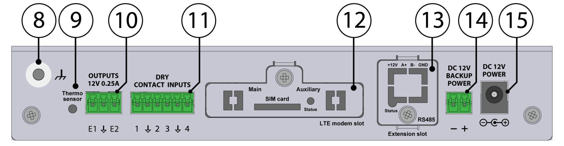
Rear view: chassis ground, temperature sensor, relay outputs, dry contacts, modem and expansion slot, power supply.
Chassis ground
M4 thread. Increases resistance to conducted and radiated RF interference. Connection should be carried out by a qualified electrician.
Temperature sensor
Integrated sensor with an accuracy of ±1 °C.
Outputs 12V / 0.25A
Terminal blocks (electronic relay) for each output, 3.81 mm pitch, 3-pin, with dedicated status LEDs (E1/E2) on the front panel.
Dry contacts 1–4
Digital inputs, 3.5 mm pitch, 6-pin.
Modem slot
Slot for an optional LTE modem (sold separately) for remote monitoring without a fixed IP network.
Expansion slot
Accommodates one of two expansion modules: Modbus/RTU expansion or OSDPv2 reader expansion. Only one expansion module can be installed at a time.
DC 12V backup power
Alternative power supply, 12V DC / 2A, 3.81 mm pitch, 2-pin.
DC 12V power
Main power input, 12V DC / 2A.
Wiring diagram
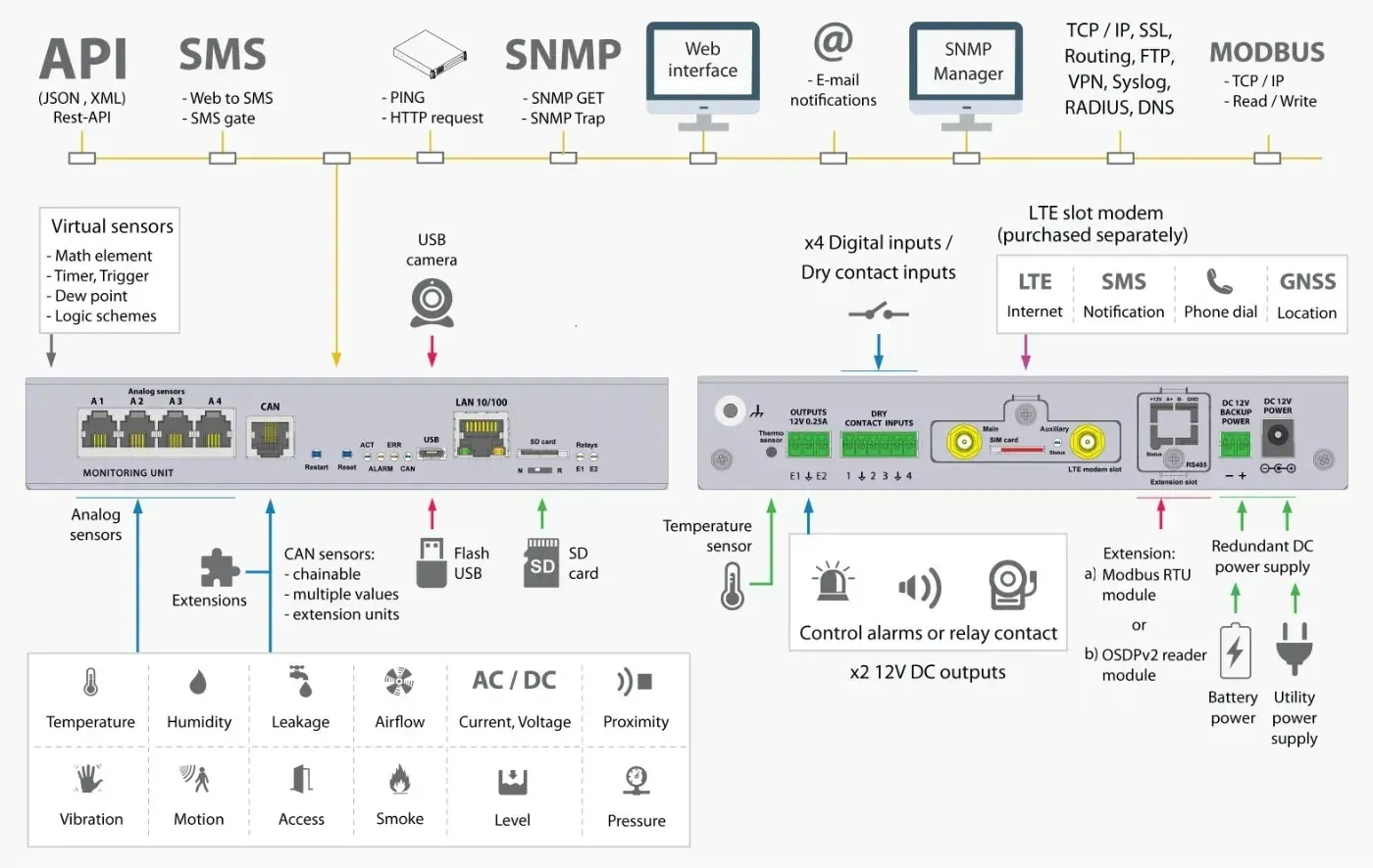
Complete wiring diagram of all ports, outputs, and expansion options of the 100T at a glance.
What's included in the box
Please check the delivery for completeness upon receipt and report any missing or damaged parts to your supplier immediately.
- Didactum 100T monitoring unit1 piece
- 12V power adapter1 piece
- RJ-45 Ethernet cable, 3 m1 piece
- OTG USB cable1 piece
- Terminal block, 3-pin, 3.5 mm1 piece
- Terminal block, 3-pin, 3.81 mm1 piece
- Terminal block, 2-pin, 3.81 mm1 piece
- Self-adhesive rubber feet4 pieces
- Quick start guide1 piece
Dimensions in detail
Technical Specifications
Device management
| Device management | Web, SNMP |
|---|---|
| Sensor access | Three-tier login (user management) |
Interface
| LAN | Ethernet 10 / 100 / 1000 Mbit |
|---|---|
| Operating system | Linux v.6.2 |
| Interface | Any browser |
| Memory (RAM) | 128 MB |
| CPU speed | 720 MHz |
| Total CPU cores | 2 |
| Clock | Built-in clock |
| Timer | Built-in watchdog |
| USB | 1× USB 2.0 Type-C |
Sensors & Logic
| Max. number of sensors | 100 (physical sensors, dry contacts, relays) |
|---|---|
| Max. number of elements | 700 (notifications, triggers, timers, logic, sensors, etc.) |
| Virtual functions | Ping monitoring, SNMP GET/traps, logic schemes, triggers, timers, virtual calculations (math element), Modbus TCP/IP read/write |
Network / Protocol Support
| LTE gateway mode | Optional, via LTE modem |
|---|---|
| LTE access mode | Optional, via LTE modem (incl. SMS/web-to-SMS) |
| Network protocols | DHCP, HTTP, HTTPS, SNMP (v1/v2c/v3), SMTP, FTP, syslog, TLS (v1.0–1.3) |
| Modbus RTU | Optional, Modbus RTU expansion module |
| Modbus TCP/IP | Yes |
| RS485 / OSDPv2 | Optional, OSDPv2 RS485 expansion module |
| VPN (secure data transfer) | Supported (incl. SSL) |
| DynDNS, static routing, RADIUS | Supported |
Notifications
| Alarm types | Email, FTP, syslog, SMTP, SNMP traps, SMS (optional), web-to-SMS |
|---|---|
| Max. email recipients | 20 |
| Max. SMS recipients | 20 |
Power supply
| Power input (230V AC) | No |
|---|---|
| Power input (24–48V DC) | Optional |
| Power input (12V DC) | Input (main and backup supply) |
| Redundant power supply | DC/DC, with PTC fuse |
| Min. power consumption | 1 W |
| Max. power consumption | 10 W |
Inputs/Outputs
| Analog port | 4 built-in ports, expandable via CAN bus |
|---|---|
| CAN port | 1 port, up to 32 devices (24 recommended) |
| Dry contact inputs | 4 |
| Relay outputs (240V / 10A) | No |
| Relay outputs (12V / 0.25A) | 2 |
Video support
| USB cameras | 1 |
|---|---|
| IP cameras | up to 4 (display only) |
Storage & Logs
| MicroSD slot | Up to 512 GB |
|---|---|
| USB export | Logs, sensor data, settings |
| Log delivery | Syslog, FTP, email |
| Storage duration | Up to 3 years |
| Sampling rate | 1 second |
Built-in Sensors & LEDs
| Temperature sensor | Built-in, ±1 °C accuracy |
|---|---|
| Voltage sensor | Main and backup supply |
| LED indicators | LAN (link/activity), system status & error, alarm status, CAN bus status |
Environmental Conditions
| Operating temperature | -10 to +70 °C |
|---|---|
| Storage temperature | -25 to +85 °C |
| Operating humidity | 0 to 90% (non-condensing) |
| Storage humidity | 0 to 95% (non-condensing) |
Mechanics & Housing
| Installation | Desktop |
|---|---|
| Housing material | Metal |
| Dimensions (L × W × H) | 180 × 35 × 80 mm |
| Weight | approx. 0.7 kg |
| Reset/recovery switch | Present |
Frequently Asked Questions
What is the Didactum Monitoring System 100T and what is it used for?
The Didactum Monitoring System 100T is a professional IP-based monitoring solution for IT infrastructures and critical environments. It continuously monitors key parameters such as temperature, humidity, voltage, leaks, smoke, and airflow, making it ideal for server rooms, data centers, production facilities, and branch locations. It also functions as an I/O controller for controlling doors, fans, generators, UPS systems, and circuit breakers.
What sensors can be connected to the system?
The Monitoring System 100T has 4 analog sensor ports directly on the device and can be expanded via CAN bus to up to 32 additional devices – including temperature, humidity, smoke, PIR motion, door, vibration, water, and voltage sensors. In total, up to 100 physical sensors, contacts, and relays can be managed simultaneously.
How are alarms and notifications sent?
The system offers various alerting methods: email notifications to up to 20 recipients, SMS delivery (optional via LTE modem) to up to 20 recipients, SNMP traps for network management systems, syslog messages, and FTP transfer. In addition, external sirens or strobe lights can be connected via the relay outputs. Alarm rules are individually configurable with various thresholds and escalation levels.
Can the system be integrated into existing IT infrastructures?
Yes. The system supports SNMP v1/v2c/v3, Modbus TCP/IP, and, via expansion modules, Modbus RTU and OSDPv2, and can be integrated into common monitoring platforms such as Nagios, PRTG, Zabbix, Check_MK, or OpenNMS. It connects via Gigabit Ethernet and can be managed both through the web interface and via network management tools.
What do the modem and expansion slots do?
The modem slot accommodates an optional, separately available LTE modem, enabling remote monitoring and the sending of alarm messages even without a fixed IP network. The expansion slot accommodates either a Modbus/RTU expansion or an OSDPv2 reader expansion – only one of the two modules can be installed at a time.
What power supply does the system require and how fail-safe is it?
The Monitoring System 100T is powered by a 12V DC power supply and additionally features a separate 12V DC backup power input for redundant DC/DC power supply with a PTC fuse. All events are permanently logged and stored on the MicroSD slot for up to 3 years, and a built-in watchdog ensures automatic restarts in the event of system errors.
Questions about the 100T?
Our support team in Germany will be happy to advise you free of charge on selection, setup, and sensors.
Scope of delivery
- 1 x Didactum 100T monitoring device
- 1 x 12V power supply
- 1 x RJ-45 3m power cable
- 1 x OTG USB cable
- 1 x Terminal 3P adapter, 3.5 mm
- 1 x terminal 3P adapter, 3.81 mm
- 1 x terminal 2P adapter, 3.81 mm
- 4 x self-adhesive rubber feet
- 1 x quick start guide
Manufacturer information:
Didactum® Security GmbH
Im Mühlenfeld 4
48163 Münster
Germany
Phone: +49 - 171 - 33 11 577
Email: info@didactum-security.de
