


Didactum Knowledge Base · Didactum Devices
Didactum PDU 8T
Overview of the device, its connectors and technical specifications of the Didactum PDU 8T – the switched power distribution unit with 8 C13 outlets, SNMP connectivity, built-in sensor ports and an optional LTE modem for 19" technical, switch and server racks.


What sets the PDU 8T apart
Switched power distribution with integrated sensor monitoring – for targeted protection and remote control of IT equipment.
8 switchable C13 outlets
Switchable individually or as a group manually, via SNMP, or sensor-controlled.
Up to 100 sensors
8 analog ports directly on the device, expandable via CAN bus to up to 32 devices.
Real-time alerting
Via email, SMS, SNMP trap, syslog, or a connected siren.
Web-based & SNMP
Compatible with Zabbix, PRTG, Nagios and Check_MK, without any additional software.
I/O control
Additional control of doors, fans, generators, UPS units and circuit breakers.
Scalable
Up to 700 elements – notifications, triggers, timers, logic schemes.
LTE modem & SMS
Optional LTE modem for remote monitoring and switching on/off via SMS command.
Video surveillance
Optional USB camera plus display of up to 4 IP cameras in the web interface.
Made in EU
19" rack mounting brackets included, German support included.
Typical application examples
- Remote switching on and off of server and IT equipment
- Rebooting unresponsive PC, server and storage systems
- Out-of-band management via SMS remote command (LTE modem required)
- Automatic shutdown of heat-sensitive systems in case of overtemperature in the rack
- Immediate shutdown of consumers during UPS battery operation
- Protection against water damage through immediate power shutdown in case of a leak
- Physical environmental monitoring (temperature, humidity) in the rack
- Rack monitoring and integration with DCIM/NMS systems
Connectors & Controls
All ports, outlets and LEDs on the front and rear of the PDU 8T, plus the complete connector and function diagram at a glance.
The PDU 8T separates the control/sensor side from the power side: the front panel holds the 19" rack mounting brackets, the 2 analog sensor inputs, LAN, USB, the modem slot, and all status LEDs (operation, error, alarm, CAN bus, relay and outlet status). The rear panel houses the 8 switchable C13 outlets, the power inlet (IEC C20) with fuse, the relay and dry-contact connectors, the two CAN connectors, the SD card slot, the Modbus RTU/OSDPv2 expansion slot, the chassis ground, the DC 12V backup power supply, the built-in temperature sensor, the restart/factory-reset buttons and the DIP switch for system recovery.
Front view

Front view: rack mounting brackets, analog sensors A1–A2, LAN, USB, modem slot, status LEDs.
1U 19" rack mounting brackets
2× brackets for mounting the PDU in a 1U 19" rack slot.
Analog sensors A1–A2
2× RJ12 connectors for analog sensors with automatic detection (AutoSense).
LAN port
10/100/1000 Base-T Ethernet connector. Orange LED indicates network traffic, green LED indicates connection status (steady green = connected, blinking = connecting/system startup).
USB
Micro-USB port – for USB camera recording and USB flash drives for system logs and system recovery.
Modem slot
Accepts an optional LTE slot modem (sold separately) for remote monitoring without a fixed IP network.
Label area
Space for a label, e.g. to identify the system with its IP address.
Status LEDs (Activity, Error, Alarm, CAN, E1/E2, R1–R8)
Activity (green) shows system status (operation: 2 Hz blinking, successful update: 4 Hz blinking). Error (red) indicates faults and data traffic. Alarm is freely programmable via the web interface. CAN (green) shows bus status. E1/E2 show the status of the 12V/0.25A relay outputs, R1–R8 show the switching state of the 8 C13 outlets.
Rear view

Rear view: C13 outlets, power inlet, relay and dry-contact connectors, CAN, SD card, expansion slot, chassis ground, temperature sensor, DIP switch.
Outlets 1–8 (C13)
8× C13 outlets, 110–240V AC, 50/60 Hz, switchable individually or as a group.
Power inlet
C20 inlet, 110–240V AC, 50/60 Hz.
Inlet fuse
16A fuse to protect the PDU and connected consumers.
12V / 0.25A outputs
Terminal outputs (electronic relay) for each output, with dedicated status LEDs (E1/E2) on the front panel.
Dry contact inputs 1–2
Digital inputs (type IN), e.g. for reed contacts, fire alarm or UPS systems.
CAN
One digital RJ12 connector for connecting CAN sensors, expansions, and devices on a CAN bus; cascadable.
SD card
MicroSD card slot with eject mechanism – for data storage or system recovery.
Expansion slot
Accepts a Modbus/RTU or an OSDPv2 reader expansion module (sold separately). Only one of the two expansions can be installed at a time.
Chassis ground
M4 thread. Improves immunity to conducted and radiated RF interference; connection should be made by a qualified electrician.
DC 12V backup power
Connector for the backup power supply.
Temperature sensor
Built-in sensor with an accuracy of ±1 °C.
Restart / factory reset button
Restart: hold for 2 seconds and release to restart the system. Factory reset: hold for longer than 5 seconds – the Error LED starts blinking; after 20–60 seconds the device is reset and reachable again once the Activity LED blinks.
DIP switch (N–R)
Normal mode: switch set to the left (should always be in this position). Recovery: switch set to the right, loads the clean system image from the SD card.
Connector and function diagram
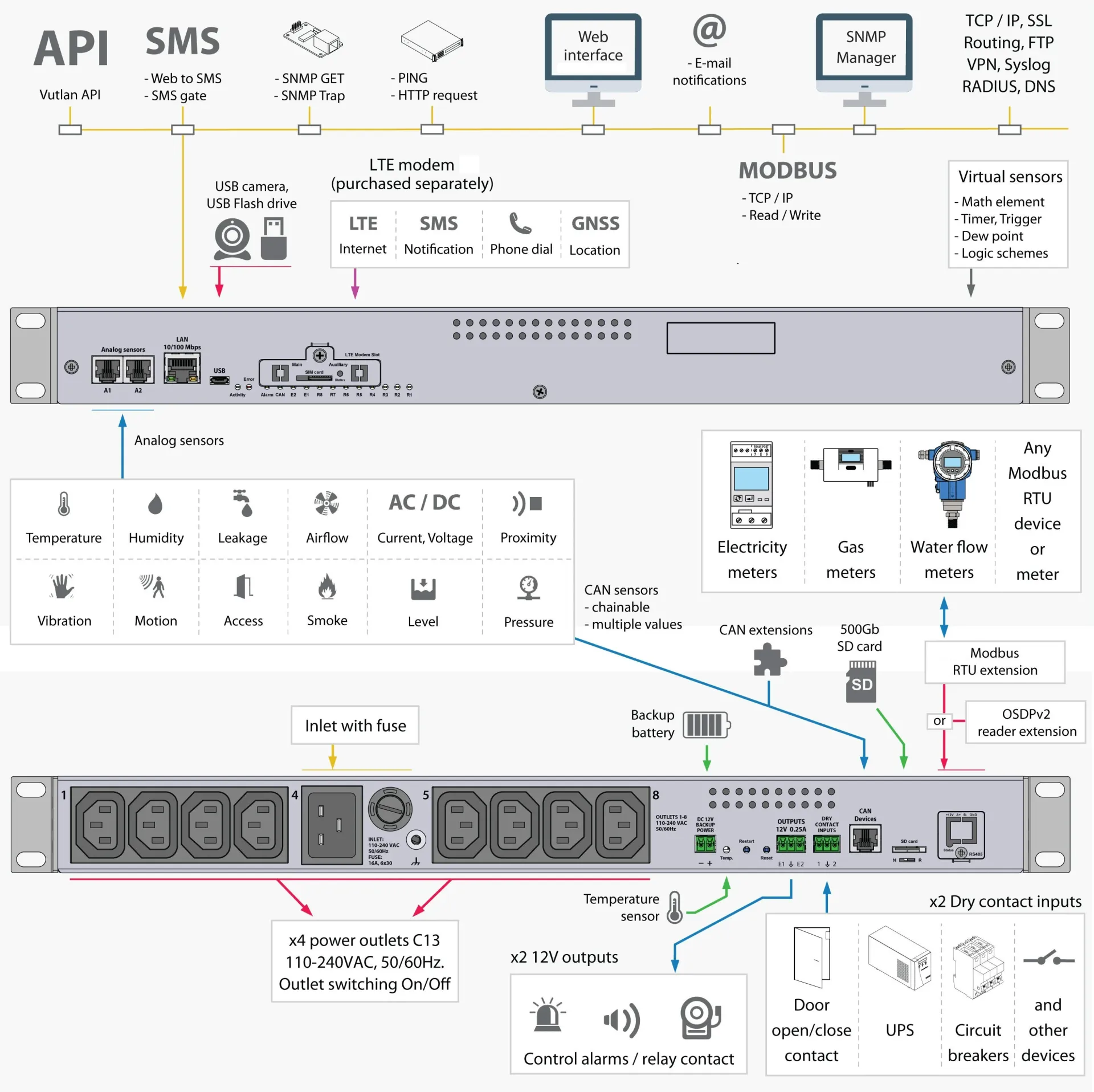
Complete connector and function diagram of all ports, outputs, and expansion options of the PDU 8T at a glance.
What's included in the delivery
Please check the scope of delivery upon receipt for completeness and report any missing or damaged parts to your supplier immediately.
- Didactum PDU 8T monitoring device1 piece
- EU Schuko-to-C13 cable, 0.75 mm², 230V, 10A1 piece
- IEC C13 socket to IEC C14 plug power cable1 piece
- RJ-45 patch cable (LAN/Ethernet), 3 m1 piece
- Micro-USB to USB adapter cable1 piece
- Connector plug, 3-pin, 3.81 mm1 piece
- Connector plug, 3-pin, 3.5 mm1 piece
- Connector plug, 2-pin, 3.81 mm1 piece
- 19" rack mounting brackets2 pieces
- Phillips flat-head screws, M3 × 8 mm6 pieces
- Self-adhesive rubber feet4 pieces
- Quick start guide1 piece
Dimensions in detail
Technical Specifications
Device management
| Device management | Web, SNMP |
|---|---|
| Physical sensors | CAN, Analog |
| Virtual sensors (e.g. Modbus TCP) | Yes |
Interface
| LAN | Ethernet 10/100 Mbit |
|---|---|
| Operating system | Linux |
| Interface | Any browser |
| Memory (RAM) | 128 MB |
| CPU speed | 720 MHz |
| Total CPU cores | 2 |
| Clock | Built-in clock |
| Timer | Built-in watchdog |
| USB | 1× USB 2.0 Type-C |
Sensors & logic
| Max. number of sensors | 100 (physical sensors, dry contacts, relays) |
|---|---|
| Max. number of elements | 700 (notifications, triggers, timers, logic, sensors, dry contacts, SNMP Get/Trap, etc.) |
| Temperature sensor | ±1 °C board temperature, built-in |
Network / protocol support
| LTE gateway mode | Optional, via separately available LTE modem |
|---|---|
| Network protocols | DHCP, HTTP, HTTPS, SNMP (v1/v2c/v3), SMTP, FTP, Syslog, TLS |
| Modbus TCP/IP | Yes |
| Modbus RTU (RS-485) | Optional, via expansion module |
| OSDPv2 reader expansion | Optional, via expansion module |
| VPN / SSL | Supported |
| DynDNS, static routing, RADIUS | Supported |
Notifications
| Alarm types | Email, FTP log, syslog, SMTP, SNMP traps, SMS (modem sold separately), web-to-SMS |
|---|---|
| Max. email recipients | 20 |
| Max. SMS recipients | 20 |
| Ping function | Built-in server ping function |
Power supply
| Inlet | IEC C20, 110–240V AC, 50/60 Hz |
|---|---|
| Outlets | 8× C13, switchable |
| Fuse | 16 A (PTC) |
| Power metering at outlets | No |
| Backup power input terminal | DC 12V emergency power supply, 3.81 mm, 2-pin |
| Min. power consumption | 1 W |
| Max. power consumption | 6 W |
Inputs/outputs
| Analog port | 2 built-in ports (A1–A2), expandable via CAN bus |
|---|---|
| CAN port | 1 port, max. 32 devices |
| Dry contact inputs | 2 |
| Max. dry contact outputs | 5 (relay/digital outputs) |
| Relay outputs (12V / 0.25A) | 2 |
Video support
| USB cameras | 1 |
|---|---|
| IP cameras | up to 4 (display only) |
Storage & logs
| MicroSD slot | Up to 512 GB (SDXC), FAT32 formatting possible |
|---|---|
| USB export | Logs, sensor data, settings |
| Log transmission | Syslog, FTP, email |
| Max. number of log files | 10,000 logs/day ≙ 27 years |
Mechanics & housing
| Mounting | 19" rack (1U), brackets included |
|---|---|
| Housing material | Plastic |
| Dimensions (L × W × H) | 440 × 44 × 107 mm |
| Weight | approx. 2.38 kg |
| External chassis ground | Yes |
Web interface panels
| Dashboard panel | Yes |
|---|---|
| Overall statistics panel | Yes |
| System tree panel | Yes |
| Dry contact outputs/inputs panel | Yes |
| Camera panel | Yes |
Frequently asked questions
What is the Didactum PDU 8T and what is it used for?
The Didactum PDU 8T is an SNMPv1-, SNMPv2c- and SNMPv3-compatible, IP-based power strip with 8 switchable C13 outlets for 19" technical, switch, network and server racks. It is used for remote switching on/off and rebooting of server and IT equipment, as an I/O controller for doors, fans, generators and UPS units, and for physical environmental monitoring in the rack.
How many outlets does the PDU 8T have and how are they switched?
The PDU offers 8 switchable C13 outlets, which can be switched individually or as a group manually via the web interface, via an SNMP command, or automatically via connected sensors (e.g. in case of overtemperature or UPS battery operation).
Which sensors can be connected to the PDU 8T?
The PDU 8T has 2 analog sensor ports (A1–A2) directly on the device and can be expanded via the CAN bus to up to 32 additional devices – including temperature, humidity, smoke, door, and water sensors. In total, up to 100 physical sensors, contacts, and relays can be managed simultaneously.
How are alarms and notifications sent?
The PDU 8T offers email notifications to up to 20 recipients, SMS delivery (optional, via LTE modem) to up to 20 recipients, SNMP traps for network management systems, and syslog and FTP transmission. In addition, external sirens or beacon lights can be connected via the 12V relay outputs.
Can the PDU 8T be controlled remotely via SMS?
Yes. With the optional LTE modem, the connected C13 outlets can be switched on and off via SMS command even in the event of a network or DSL outage. Every switching command is acknowledged by the PDU via SMS, ensuring reliable confirmation of execution.
What do the modem and expansion slots do?
The modem slot accepts an optional, separately available LTE modem and enables remote monitoring and SMS remote commands without a fixed IP network. The expansion slot accepts either a Modbus/RTU or an OSDPv2 reader expansion – only one of the two modules can be installed at a time.
Can the PDU 8T be integrated into existing monitoring systems?
Yes. The PDU 8T supports SNMP v1/v2c/v3 as well as Modbus TCP/IP and – via expansion modules – Modbus RTU and OSDPv2. It can be integrated into common platforms such as Nagios XI, check_MK, openITCOCKPIT, OpenNMS, PRTG, WhatsUp Gold, or Zabbix; the required MIB files are included in the scope of delivery.
What is the difference between the PDU 8T and the PDU 4T?
The PDU 8T offers 8 switchable C13 outlets instead of 4, and a C20 inlet with a 16A fuse (the PDU 4T uses C14 with 10A). Both devices share the same control platform with identical sensors, logic, and notification features; at 440 × 44 × 107 mm, the PDU 8T is slightly taller to accommodate the additional outlets.
Questions about the PDU 8T?
Our support team in Germany will be happy to advise you free of charge on selection, setup, and sensors.
Scope of delivery
- 1 x Didactum PDU 8T monitoring device
- 1 x EU Schuko C13 0. 75 мм2 230V 10A cable
- 1 x IEC C13 socket to IEC C14 plug power cable
- 1 x RJ-45 3m patch cable, LAN/Ethernet cable
- 1 x MicroUSB to USB adapter cable
- 1 x 3-pin connector plug, 3, 81 mm
- 1 x connector plug 3-pin, 3.5 mm
- 1 x connector plug 2 pins, 3.81 mm
- 2 x 19" rack brackets
- 6 x M3 x 8mm Phillips flat head screws
- 4 x self-adhesive rubber feet
- 1 x quick start guide
Manufacturer information:
Didactum® Security GmbH
Im Mühlenfeld 4
48163 Münster
Germany
Phone: (+49) 2501 92 90 160
Email: info@didactum-security.de

Extension modules


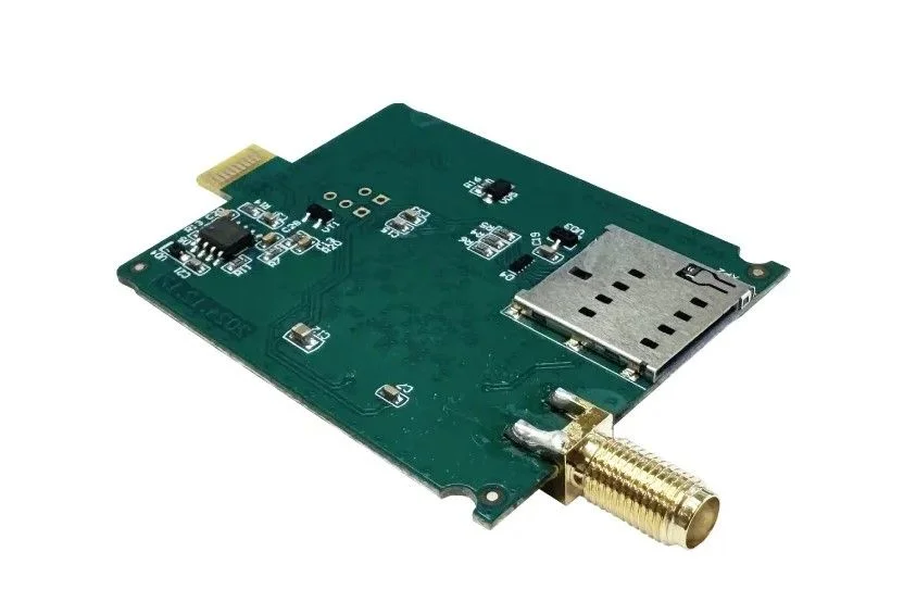


Extension units


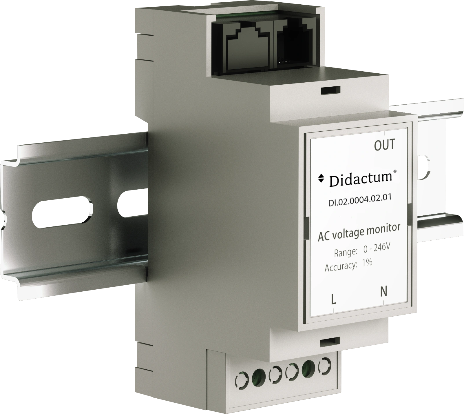
Suitable sensors


Current Measurement via Hall Effect Current Transformer Directly in the Monitoring System The Didactum current transformer transmits the current values measured by a Hall effect current transformer to a Didactum monitoring system. This analog plug-and-play converter is connected to any analog port (A1 to A8) of a Didactum monitoring system or expansion unit and works with Hall effect current transformers with a 0–5V output signal and 12V DC power supply. This article describes both available variants of the current transformer together: the AC variant for AC measurements and the DC variant for DC measurements. Both variants are identical in design, connection, and functionality, but differ in the type of external Hall effect current transformer they work with. The choice between AC and DC is made directly during the ordering process via the variant selection on this product page. Configuration Individually configurable: AC or DC The Didactum current transformer is already tailored during the ordering process to match the type of Hall effect current transformer already in use or planned. ⚠️ Please note: The correct variant must be actively selected above the shopping cart button under “Select variant”. The AC variant works only together with an AC Hall effect current transformer, while the DC variant works only together with a DC Hall effect current transformer. An incorrect combination will not provide correct measurement values. Select variant AC For monitoring AC current meters. Suitable for use with AC Hall effect current transformers for measuring alternating current. DC For monitoring DC current meters. Suitable for use with DC Hall effect current transformers for measuring direct current. Both variants are identical in connection, structure, and function; details can be found in the “Structure” section below. Structure Current transformer connections The current transformer has only a few, clearly separated connections for input, output, and the external current transformer. 1 Input: 3-pin terminal block 2.54 mm pitch. The external Hall effect current transformer is connected here using 3 wires (0–5V signal and 12V DC power supply). 2 Output: RJ11 6P4C Connects the current transformer via RJ11 cable to an analog port (A1 to A8) of the Didactum monitoring system or a VT408 expansion unit. The 12V DC power supply for the external Hall effect current transformer is provided by the Didactum monitoring system via the analog port and passed through by the current transformer to the current transformer sensor. A separate power supply for the current transformer sensor is not required. Required components Matching Hall effect current transformer required The Didactum current transformer cannot be operated on its own. It absolutely requires an external Hall effect current transformer with 0–5V output and 12V DC supply, which performs the actual current measurement on the line. HALL AC current transformer Open AC current transformer for alternating current, available for measurement ranges from 5 to 50 A. AC current transformer AC current transformer for higher alternating currents, available for measurement ranges from 50 to 500 A. DC current transformer DC current transformer for direct current, available for measurement ranges from 50 to 500 A. Alternatively, any other commercially available Hall effect current transformer with a suitable 0–5V output signal and 12V DC supply can also be used. Installation Install current transformer and sensor together The current transformer sensor and Didactum current transformer are installed together. 1 Mount the current transformer sensor Secure the Hall effect current transformer with screws and nuts. The line to be measured is guided through the aperture of the current transformer. 2 Connect to the monitoring system Connect one end of the RJ11 cable to a free analog port (A1 to A8) of the Didactum monitoring system and the other end to the RJ11 port of the current transformer. 3 Wire the current transformer sensor Connect the 3 wires to the Hall effect current transformer according to the wiring diagram using the 3-pin terminal block of the current transformer. ⚠️ Safety instructions: Observe the applicable regulations for installation in the respective country as well as the relevant accident prevention regulations, in addition to internal company work, operating, and safety rules. The specified technical limits, especially the permissible ambient temperature range, must not be exceeded under any circumstances. Also check the maximum insulation voltage of the current transformer sensor and the maximum permissible cable diameter of the line to be measured before installation. Web interface Full control over thresholds, trends, and automation The current transformer integrates seamlessly into the Didactum web interface and delivers precise measurement values as well as actionable insights. Individual thresholds (Lower Critical, Lower Warning, Normal, Upper Warning, Upper Critical) per measurement point Logic schemes for automated actions when limit values are exceeded, e.g. in case of overload Clear, individually configurable dashboard Graphical trend display and continuous logging of measurement values Notifications via email, SMS, SNMP trap, and other channels Use cases Areas of application for the current transformer Monitor circuits and outgoing feeders in electrical distribution boards to detect overloads Monitor power consumption of critical IT and facility equipment in the data center Measure generator load and detect over- or underload Monitor input and output current of UPS systems to assess backup performance Monitor motors, pumps, compressors, and production machines for load changes Record charging and discharging currents of battery banks and energy storage systems Check the power yield of solar inverters and other renewable energy systems Detect wear or defects early based on changed current consumption Scope of delivery What is included in the package Please check the contents upon receipt for completeness and report any missing or damaged parts to your supplier immediately. The external Hall effect current transformer (AC or DC) is not included in this scope of delivery and must be ordered separately. Didactum current transformer (AC or DC, depending on the ordering option)1 piece RJ11 cable 6P4C, 2 m1 piece 3-pin terminal block, 2.54 mm1 piece 3-pin terminal block, 3.81 mm1 piece 3-wire connection cable, 2 m1 piece Screw B4.2 x 16 mm1 piece Self-adhesive label1 piece Benefits at a glance Why this current transformer is the right choice High accuracy1% measurement accuracy in signal transmission from the current transformer sensor. AC and DC availableSelect the matching variant for alternating or direct current measurement. Plug and playAutomatic detection at the analog port, no manual setup required. No separate power supplyThe 12V supply for the current transformer sensor is provided directly via the analog port. CompactSmall form factor (80 × 19 × 20 mm), desktop or wall mounting. Long rangeUp to 50 m distance to the monitoring system or expansion unit. ExpandableAdd additional current transformers easily via the VT408 expansion unit. Made in EUDeveloped and manufactured in the European Union. FAQ Frequently asked questions What is the difference between the AC and DC variants? Both variants are identical in connection and function. The AC variant is intended for use with AC Hall effect current transformers for AC measurement, while the DC variant is intended for use with DC Hall effect current transformers for DC measurement. The correct variant is selected during ordering via the options menu. Can I use the AC variant with a DC current transformer sensor? No. The AC variant works only with AC Hall effect current transformers, and the DC variant works only with DC Hall effect current transformers. An incorrect combination will not provide correct measurement values. Is the external Hall effect current transformer included in the package? No. The Didactum current transformer absolutely requires an external Hall effect current transformer with a 0–5V output and 12V DC supply, which must be ordered separately. How is the current transformer connected? The current transformer is connected via RJ11 cable to any analog port (A1 to A8) of the Didactum monitoring system. The external Hall effect current transformer is connected via a 3-wire cable to the 3-pin terminal block of the current transformer. Does the current transformer sensor need its own power supply? No. The 12V DC supply for the current transformer sensor is provided by the Didactum monitoring system via the analog port and passed through by the current transformer. Can the current transformer be operated independently without a monitoring system? No. The current transformer itself provides no display or analysis and must always be used together with a Didactum or Vutlan monitoring system and a suitable external Hall effect current transformer. Questions about the Didactum current transformer? Our support team in Germany will advise you free of charge on selection, installation, and configuration. Contact form (+49) 2501 92 90 160

Precise Probe for DC Current Measurement The Didactum DC current transformer probe is a simple, open-loop Hall-effect DC current transducer that measures direct current on a cable contactlessly, without interrupting it. The cable to be measured is routed through the opening of the ring-shaped transducer; the probe converts the measured DC current into a proportional 0–5V DC output signal. This article refers to the DC-100 model with a rated current of 100A and a measurement range of 0–100 A — ideal for monitoring battery systems, DC busbars, and DC distribution lines. ⚠️ Important note: The Didactum DC current transformer probe measures the current on the cable, but cannot transmit the measured signal to a monitoring system on its own. The Didactum current transducer in the DC version, item no. DI14030-DC, is additionally required as a transceiver. It receives the probe’s 0–5V signal and forwards it via an analog port (A1…A8) to the Didactum monitoring system. Without the DI14030-DC, no display, evaluation, or alarm notification of the measured values is possible. Design Design of the Current Measuring Probe The current measuring probe consists of a ring-shaped transducer head with a pass-through opening and a 4-pin terminal block. 1 Pass-through opening (Ø 21 mm) The DC cable to be measured is routed through this opening in the ring-shaped toroidal transducer core. The probe measures the current contactlessly via the magnetic field generated. 2 Mounting tabs Two mounting tabs on the housing used to secure the probe with screws and nuts. 3 4-pin terminal block (3.81 mm pitch) Four-wire terminal for connection to the Didactum current transducer DI14030-DC. Pin assignment: G (Ground), M (0–5V measurement signal), G (Ground), + (+12V DC supply). Installation Mounting and Connection The current measuring probe and the Didactum current transducer (DI14030-DC) are installed together. 1 Mount the probe Secure the current measuring probe in a suitable location using screws and nuts. Route the DC cable to be measured through the probe’s pass-through opening. 2 Wiring to current transducer DI14030-DC Connect the 4 wires of the terminal block (G, M, G, +) to the 3-pin input terminal of the Didactum current transducer (DI14030-DC, DC version) according to the pin assignment. 3 Connect to the monitoring system Connect the Didactum current transducer (DI14030-DC) via RJ11 cable to a free analog port (A1…A8) of the Didactum monitoring system or an 8-port sensor expansion unit. ⚠️ Safety instructions: Comply with the applicable regulations for installation in the respective country as well as the relevant accident prevention regulations, and also with internal operating, work, and safety rules. The specified technical limits, in particular insulation voltage, pass-through diameter, and ambient temperature range, must under no circumstances be exceeded. Before installation, check the maximum permissible cable diameter and the maximum insulation voltage of the probe. Web interface Full Control over Thresholds, Trends, and Automation Via the Didactum current transducer (DI14030-DC), the probe integrates seamlessly into the Didactum web interface. Individual thresholds (Lower Critical, Lower Warning, Normal, Upper Warning, Upper Critical) for each measuring point Logic schemes for automated actions when limits are exceeded, e.g. in case of overload or deep discharge Clear, individually configurable dashboard Graphical trend display and continuous logging of measured values Notifications by email, SMS, SNMP trap, and additional channels Applications Use Cases for the Current Measuring Probe Monitoring load current on DC Hall probes for battery strings, DC busbars, and distribution lines for remote power consumption monitoring Detecting overload and assessing the condition of DC circuits Monitoring charging and discharging currents in battery banks, UPS systems, and energy storage systems Detecting anomalous current flow to optimize battery lifespan Monitoring telecom rectifiers, DC motors, solar charge controllers, EV charging stations, and industrial DC loads Detecting operating changes, unexpected load fluctuations, and fault conditions in DC systems Scope of delivery What Is Included Please check the contents upon receipt for completeness and report any missing or damaged parts to your supplier immediately. The Didactum current transducer DI14030-DC is not included in this scope of delivery and must be ordered separately. Didactum DC current transformer probe DC-100 (100A)1 piece Self-adhesive label1 piece Screw L18.5 M42 pieces Bolt L14 M42 pieces Nut M3.52 pieces Key benefits Why This Current Measuring Probe Is the Right Choice 100A rated currentMeasurement range 0–100 A for battery systems, DC busbars, and distribution lines. Contactless measurementDetects DC current without disconnecting the cable. High accuracyAccuracy and linearity error of ≤ ±1.0%. Fast response timeResponse time of ≤ 20 ms for timely readings. Easy installationMounted using two tabs with screws and nuts. Robust insulationInsulation voltage AC 2.5 kV 50 Hz 1 min for safe operation. Wide operating rangeDesigned for ambient temperatures from -10 °C to +70 °C. Made in EUDeveloped and manufactured in the European Union. FAQ Frequently Asked Questions What current range is this model suitable for? This model (DC-100) has a rated current of 100A and covers a measurement range of 0–100 A. Make sure the maximum expected operating current of the monitored cable stays safely within this range. Can the current measuring probe be connected directly to the monitoring system? No. The probe provides a 0–5V analog signal and requires the Didactum current transducer in the DC version (DI14030-DC) as a transceiver to transmit this signal to an analog port of the monitoring system. Is DI14030-DC included in the package? No. The Didactum current transducer DI14030-DC is a separate product and must be ordered additionally unless already available. Does the cable need to be cut for installation? No. The current measuring probe measures contactlessly through the magnetic field of the cable routed through the pass-through opening. Cutting the cable is not required for measurement. Can multiple current measuring probes be used at the same time? Yes. Each DC circuit to be monitored requires its own DC-100 current measuring probe with its own Didactum current transducer (DI14030-DC) on a free analog port. If the available ports are not sufficient, the number can be increased using an 8-port sensor expansion unit. Is the probe also suitable for AC measurements? No. The Didactum DC current transformer probe is designed exclusively for direct current (DC). For AC measurements, a separate product is available that is combined with the AC version of the Didactum current transducer. Questions about the Didactum DC current transformer probe? Our support team in Germany will advise you free of charge on selection, installation, and configuration. Contact form (+49) 2501 92 90 160


Precise Hall-Effect Current Transformer for AC Measurement The Didactum AC current transformer is a simple, open-loop Hall-effect AC current transformer (open-loop ammeter) that measures current on a conductor contactlessly without disconnecting it. The conductor to be measured is passed through the opening of the ring-shaped transformer; the transformer converts the measured AC current into a proportional 0–5V DC output signal. This article refers to model AC-100 with a rated current of 100A and a measuring range of 0–100 A — ideal for monitoring individual circuits, feeders, and medium loads. ⚠️ Important note: Although the Didactum AC current transformer measures the current on the conductor, it cannot transmit the measuring signal to a monitoring system on its own. The Didactum current transformer in the AC version, item no. DI14030-AC is additionally required; as a transceiver, it receives the 0–5V signal from the current transformer and forwards it via an analog port (A1…A8) to the Didactum monitoring system. Without the DI14030-AC, no display, evaluation, or alarming of the measured values is possible. Design Current Transformer Design The current transformer consists of a ring-shaped transformer head with a pass-through opening and a 4-pin connection terminal. 1 Pass-through opening (Ø 21 mm) The conductor to be measured is passed through this opening in the ring-shaped, toroidal transformer core. The transformer measures current contactlessly via the magnetic field that is generated. 2 Mounting tabs Two fixing tabs on the housing, used to secure the transformer with screws and nuts. 3 4-pin connection terminal (3.81 mm pitch) Four-pin terminal for wiring to the Didactum current transformer DI14030-AC. Pin assignment: G (Ground), M (0–5V measuring signal), G (Ground), + (+12V DC supply). Installation Mounting and Connection The current transformer and the Didactum current transformer (DI14030-AC) are installed together. 1 Mount the transformer Secure the current transformer in a suitable location using screws and nuts. Route the conductor to be measured through the transformer's pass-through opening. 2 Wiring to current transformer DI14030-AC Connect the 4 wires of the terminal (G, M, G, +) to the 3-pin input terminal of the Didactum current transformer (DI14030-AC, AC version) according to the wiring diagram. 3 Connect to the monitoring system Connect the Didactum current transformer (DI14030-AC) via RJ11 cable to a free analog port (A1…A8) of the Didactum monitoring system or an 8-port sensor expansion unit. ⚠️ Safety instructions: Applicable regulations for installation in the respective country and the relevant accident prevention regulations must be observed, as well as internal operational, working, and safety rules. The specified technical limits, in particular insulation voltage, pass-through diameter, and ambient temperature range, must under no circumstances be exceeded. Before installation, check the maximum permissible conductor diameter as well as the maximum insulation voltage of the transformer. Web interface Full Control of Thresholds, Trends, and Automation Via the Didactum current transformer (DI14030-AC), the current transformer integrates seamlessly into the Didactum web interface. Individual thresholds (Lower Critical, Lower Warning, Normal, Upper Warning, Upper Critical) for each measuring point Logic schemes for automated actions when thresholds are exceeded, e.g. in case of overload Clear, individually configurable dashboard Graphical trend display and continuous logging of measured values Notifications via email, SMS, SNMP trap, and other channels Applications Current Transformer Use Cases Monitor circuits and feeders in electrical distribution boards to detect overloads. Monitor the power consumption of critical IT and facility equipment in the data center. Monitor motors, pumps, compressors, and production machines for load changes. Measure generator load and detect over- or underload. Monitor input and output current of UPS systems to assess backup performance. Check the power output of solar inverters and other renewable energy systems. Automated alarming when defined current limits are exceeded. Early detection of wear or defects based on changes in current draw. Scope of delivery What Is Included Please check the scope of delivery for completeness upon receipt and report any missing or damaged parts to your supplier immediately. The Didactum current transformer DI14030-AC is not included in this scope of delivery and must be ordered separately. Didactum AC current transformer AC-100 (100A)1 pc Self-adhesive label1 pc Screw L18.5 M42 pcs Bolt L14 M42 pcs Nut M3.52 pcs Key benefits Why This Current Transformer Is the Right```xml Precision Hall-Effect Current Transducer for AC Measurement The Didactum AC current transducer is a simple, open-loop Hall-effect AC current transducer (open-loop ammeter) that measures the current on a line contactlessly without opening the circuit. The cable to be measured is passed through the opening of the ring-shaped transducer; the transducer converts the measured AC current into a proportional 0–5V DC output signal. This article refers to the AC-100 model with a rated current of 100A and a measurement range of 0–100 A — ideal for monitoring individual circuits, feeders, and medium loads. ⚠️ Important note: Although the Didactum AC current transducer measures the current on the line, it cannot transmit the measurement signal to a monitoring system by itself. The additionally required component is the Didactum current transducer in the AC version, part no. DI14030-AC, which acts as a transceiver, receives the 0–5V signal from the current transducer, and forwards it to the Didactum monitoring system via an analog port (A1…A8). Without the DI14030-AC, no display, analysis, or alarm notification of the measured values is possible. Design Design of the Current Transducer The current transducer consists of a ring-shaped transducer head with a passage opening and a 4-pin connection terminal. 1 Passage opening (Ø 21 mm) The cable to be measured is routed through this opening in the ring-shaped toroidal transducer core. The transducer measures the current contactlessly via the magnetic field generated. 2 Mounting tabs Two mounting tabs on the housing used to secure the transducer with screws and nuts. 3 4-pin connection terminal (3.81 mm pitch) Four-pole terminal block for wiring to the Didactum current transducer DI14030-AC. Pin assignment: G (Ground), M (0–5V measurement signal), G (Ground), + (+12V DC supply). Installation Mounting and Connection The current transducer and the Didactum current transducer (DI14030-AC) are installed together. 1 Mount the transducer Secure the current transducer in a suitable location using screws and nuts. Route the cable to be measured through the transducer's passage opening. 2 Wiring to the DI14030-AC current transducer Connect the 4 wires of the connection terminal (G, M, G, +) to the 3-pin input terminal of the Didactum current transducer (DI14030-AC, AC version) according to the wiring assignment. 3 Connect to the monitoring system Connect the Didactum current transducer (DI14030-AC) via RJ11 cable to a free analog port (A1…A8) of the Didactum monitoring system or an 8-port sensor expansion unit. ⚠️ Safety instructions: Comply with the applicable installation regulations in the respective country as well as the relevant accident prevention regulations, together with internal company work, operating, and safety rules. The specified technical limits, especially insulation voltage, passage diameter, and ambient temperature range, must under no circumstances be exceeded. Before installation, check the maximum permissible cable diameter and the maximum insulation voltage of the transducer. Web interface Full Control of Thresholds, Trends, and Automation Via the Didactum current transducer (DI14030-AC), the current transducer integrates seamlessly into the Didactum web interface. Individual thresholds (Lower Critical, Lower Warning, Normal, Upper Warning, Upper Critical) per measurement point Logic schemes for automated actions when limit values are exceeded, e.g. in case of overload Clear, individually configurable dashboard Graphical trend display and continuous logging of measured values Notifications via email, SMS, SNMP trap, and other channels Applications Use Cases for the Current Transducer Monitor circuits and feeders in electrical distribution panels to detect overloads Monitor the power consumption of critical IT and facility equipment in data centers Monitor motors, pumps, compressors, and production machines for load changes Measure generator load and detect overloading or underloading Monitor the input and output current of UPS systems to assess backup performance Check the output of solar inverters and other renewable energy systems Automatic alarm notification when defined current limits are exceeded Early detection of wear or faults based on changes in current draw Scope of delivery What Is Included in the Package Please check the contents of the package upon receipt for completeness and report any missing or damaged parts to your supplier immediately. The Didactum current transducer DI14030-AC is not included in this scope of delivery and must be ordered separately. Didactum AC current transducer AC-100 (100A)1 piece Self-adhesive label1 piece Screw L18.5 M42 pieces Bolt L14 M42 pieces Nut M3.52 pieces Key benefits Why This Current Transducer Is the Right Choice 100A rated currentMeasurement range 0–100 A for circuits and medium loads. Contactless measurementCurrent detection without opening the cable. High accuracy≤ ±1.0 % accuracy and linearity error. Easy installationMounting via two tabs with screws and nuts. Robust insulationInsulation voltage AC 2.5 kV 50 Hz 1 min for safe operation. Wide operating rangeDesigned for ambient temperatures from -10 °C to +70 °C. Standardized output0–5V DC signal, compatible with the Didactum current transducer DI14030-AC. Made in the EUDeveloped and manufactured in the European Union. FAQ Frequently Asked Questions Which current range is this model suitable for? This model (AC-100) has a rated current of 100A and covers a measurement range of 0–100 A. Make sure the maximum expected operating current of the monitored cable stays safely within this range. Can the current transducer be connected directly to the monitoring system? No. The current transducer provides a 0–5V analog signal and requires the Didactum current transducer in the AC version (DI14030-AC) as a transceiver to pass this signal to an analog port of the monitoring system. Is DI14030-AC included in the scope of delivery? No. The Didactum current transducer DI14030-AC is a separate product and must be ordered additionally if it is not already available. Does the cable need to be cut for installation? No. The current transducer measures contactlessly via the magnetic field of the cable routed through the passage opening. Cutting the cable is not required for measurement. Can multiple current transducers be used at the same time? Yes. Each monitored circuit requires its own AC-100 current transducer with its own Didactum current transducer (DI14030-AC) on a free analog port. If the available ports are not sufficient, the number can be expanded using an 8-port extension unit. Is the transducer also suitable for DC measurements? No. The Didactum AC current transducer is designed exclusively for alternating current (AC). For DC measurements, a separate product is available that is combined with the DC version of the Didactum current transducer. Questions about the Didactum AC current transducer? Our support team in Germany will advise you free of charge on selection, installation, and configuration. Contact form (+49) 2501 92 90 160

Compact Hall Effect Probe for Smaller AC Circuits The Didactum Small AC Current Transformer probe is a simple open-loop Hall effect AC current transducer (open-loop ammeter) in a particularly compact design that measures current on a conductor contactlessly without disconnecting it. The cable to be measured is passed through the opening of the ring-shaped transducer; the probe converts the measured AC current into a proportional 0–5 V DC output signal. This article refers to the AC-50 model with a rated current of 50 A and a measuring range of 0–50 A — ideal for individual circuits, outgoing feeders, and smaller to medium-sized loads. ⚠️ Important note: The Didactum Small AC Current Transformer probe measures the current on the conductor, but it cannot transmit the measurement signal to a monitoring system on its own. You also need the Didactum AC Current Transformer, part no. DI14030-AC, which acts as a transceiver, receives the probe’s 0–5 V signal, and forwards it via an analog port (A1…A8) to the Didactum monitoring system. Without the DI14030-AC, no display, analysis, or alarm notification of the measured values is possible. Design Current Probe Design The current probe consists of a compact ring-shaped transducer head with a pass-through opening and a 3-pin connection terminal. 1 Pass-through opening The cable to be measured is routed through the opening in the ring-shaped compact transducer core. The probe measures the current contactlessly via the magnetic field that is generated. 2 Mounting tabs Two mounting tabs on the housing used to secure the probe with screws and nuts. 3 3-pin connection terminal (pitch 3.81 mm) Three-pin terminal for wiring to the Didactum AC Current Transformer DI14030-AC. Pin assignment: + (+12 V DC supply), G (Ground), M (0–5 V measurement signal). ℹ️ Note on confusion: The AC-50 probe has a 3-pin terminal (+, G, M). The larger K6A model for higher currents uses a 4-pin terminal (G, M, G, +). When connecting, make sure the wires are assigned correctly according to the terminal labeling. Installation Mounting and Connection The current probe and the Didactum AC Current Transformer (DI14030-AC) are installed together. 1 Mount the probe Secure the current probe in a suitable location with screws and nuts. Route the cable to be measured through the probe’s pass-through opening. 2 Wiring to current transformer DI14030-AC Connect the 3 wires of the terminal (+, G, M) to the 3-pin input terminal of the Didactum AC Current Transformer (DI14030-AC) according to the wiring assignment. 3 Connect to the monitoring system Connect the Didactum AC Current Transformer (DI14030-AC) to a free analog port (A1…A8) of the Didactum monitoring system or an 8-port sensor expansion unit using an RJ11 cable. ⚠️ Safety instructions: The regulations applicable to installation in the respective country and the relevant accident prevention regulations must be observed, as well as internal company work, operating, and safety regulations. The specified technical limits, especially insulation voltage and ambient temperature range, must under no circumstances be exceeded. Before installation, check the maximum permissible conductor diameter and the maximum insulation voltage of the probe. Web interface Full Control over Thresholds, Trends, and Automation Via the Didactum AC Current Transformer (DI14030-AC), the probe integrates seamlessly into the Didactum web interface. Individual thresholds (Lower Critical, Lower Warning, Normal, Upper Warning, Upper Critical) for each measurement point Logic schemes for automated actions when limit values are exceeded, e.g. in case of overload Clear, individually configurable dashboard Graphical trend display and continuous logging of measured values Notifications via email, SMS, SNMP trap, and other channels Application examples Use Cases for the Current Probe Monitoring circuits and feeders in electrical distribution panels to detect overloads Monitoring motors, pumps, compressors, and production machines for load changes Automatic alarm notifications when defined current limits are exceeded to prevent equipment damage and power outages Monitoring the power consumption of smaller IT and facility devices in the data center Early detection of wear or defects based on changes in current consumption Complementing existing monitoring environments (Zabbix, PRTG, Nagios) Scope of delivery What Is Included Please check the delivery for completeness upon receipt and report any missing or damaged parts to your supplier immediately. The Didactum AC Current Transformer DI14030-AC is not part of this scope of delivery and must be ordered separately. Didactum Small AC Current Transformer probe AC-50 (50 A)1 piece Self-adhesive label1 piece Screw L18.5 M42 pieces Bolt L14 M42 pieces Nut M3.52 pieces Key benefits Why This Current Probe Is the Right Choice 50 A rated currentMeasuring range 0–50 A for circuits and smaller to medium-sized loads. Compact designEspecially space-saving, ideal for tight control cabinets and distribution panels. Contactless measurementCurrent detection without disconnecting the conductor. High accuracy0.5% accuracy and linearity error. Easy installationMounting via two tabs with screws and nuts. Robust insulationInsulation voltage AC 2.5 kV 50 Hz 1 min for safe operation. Wide operating rangeDesigned for ambient temperatures from -10 °C to +70 °C. Made in EUDeveloped and manufactured in the European Union. FAQ Frequently Asked Questions For which current range is this model suitable? This model (AC-50) has a rated current of 50 A and covers a measuring range of 0–60 Aac. Make sure the maximum expected operating current of the conductor being monitored stays safely within this range. How does this probe differ from the larger K6A probe? The AC-50 probe is more compact and uses a 3-pin terminal (+, G, M), while the K6A probe for higher currents uses a 4-pin terminal (G, M, G, +). Both probes require the Didactum current transformer (AC version) as the transceiver to the monitoring system. Can the current probe be connected directly to the monitoring system? No. The probe outputs a 0–5 V analog signal and absolutely requires the Didactum AC Current Transformer (DI14030-AC) as a transceiver, which transfers this signal to an analog port of the monitoring system. Is the DI14030-AC included in the scope of delivery? No. The Didactum AC Current Transformer DI14030-AC is a separate product and must be ordered additionally if not already available. Does the conductor have to be cut open for installation? No. The current probe measures contactlessly via the magnetic field of the conductor routed through the pass-through opening. Cutting the conductor is not necessary for the measurement itself. Can multiple current probes be used at the same time? Yes. Each circuit to be monitored requires its own AC-50 current probe with its own Didactum AC Current Transformer (DI14030-AC) connected to a free analog port. If the available ports are not sufficient, the number can be expanded using a VT408 expansion unit. Questions about the Didactum Small AC Current Transformer probe? Our support team in Germany will advise you free of charge on selection, installation, and configuration. Contact form (+49) 2501 92 90 160




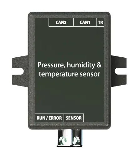
CAN sensors


Warranty extension

Software
