


Didactum Monitoring Systems
Setting up Modbus TCP & RTU
Complete guide for integrating Modbus devices: Creating virtual elements, configuring reading & writing, practical examples and tested sensors – for all Didactum devices.
☰ Table of Contents
Introduction to Modbus
⌄All Didactum Monitoring Systems support the widely used Modbus protocol – both in the TCP/IP variant and the RTU variant (RS-485). This allows external devices such as energy meters, air conditioning units, UPS systems, sensors and many other industrial devices to be directly integrated into the Didactum monitoring system.
Modbus is an open serial communication protocol originally developed by Modicon. It is used in industrial automation to communicate between a Master (here: the Didactum system) and one or more Slaves (external devices). Didactum systems always act as Modbus Master.
| Protocol | Transmission | Supported Devices | Connection |
|---|---|---|---|
| Modbus TCP | Ethernet / LAN (IP-based) | Network-capable devices with Modbus TCP support | RJ45 / LAN port |
| Modbus RTU | Serial via RS-485 bus | Sensors, meters, control devices with RS-485 | RS-485 port or USB adapter |
| Device | Modbus TCP | Modbus RTU | Note |
|---|---|---|---|
| Didactum 50T | ✔ | ✔ (with extension) | RS-485 possibly via external extension |
| Didactum 100T | ✔ | ✔ | RS-485 onboard |
| Didactum 300T | ✔ | ✔ | RS-485 onboard |
| Didactum 500T | ✔ | ✔ | RS-485 onboard |
| Didactum 550T | ✔ | ✔ | RS-485 onboard |
Modbus TCP – Creating a Reading Element
⌄A virtual “Modbus TCP (Reading)” element is used to read data from an external device via the Modbus TCP/IP protocol and display it as a measured value in the Didactum system. The Wake-on-LAN standard is also supported to wake remote devices via a network command.
- In the Didactum system web interface, click the “Add” button in the Group Tree or System Tree menu.
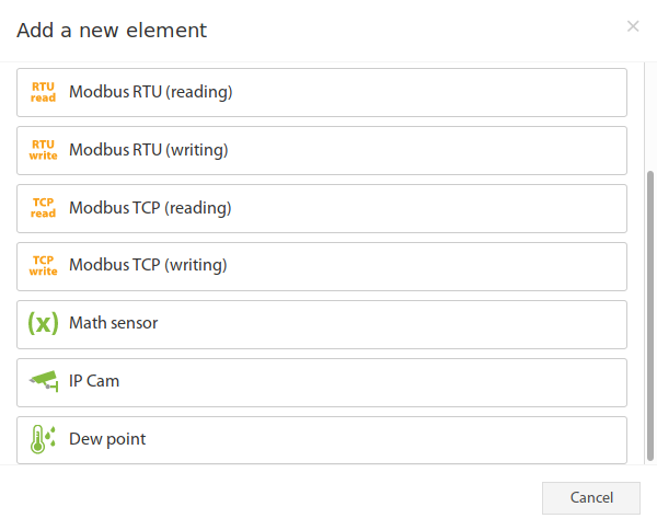
- Select “Modbus TCP (Reading)” from the selection menu – a modal window will open.
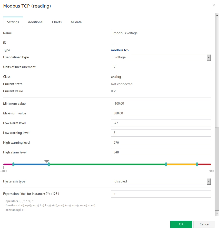
- Click on “Modbus TCP (Reading)” to open the configuration form.
 🔍 Enlarge
 🔍 Enlarge
| Field Name | Description |
|---|---|
| Name | Designation of the created element (freely selectable, e.g. „Voltage Phase L1“) |
| Custom Type | Defines the symbol displayed in the system tree (e.g. temperature, voltage, current ...) |
| Unit of Measurement | Unit in which the value is displayed in the system tree (e.g. V, A, Hz, kWh ...) |
| Minimum Value | Lower measuring range limit; if the value falls below it, the sensor changes to „Not connected“ state |
| Maximum Value | Upper measuring range limit; if the value exceeds it, the sensor changes to „Not connected“ state |
| Alarm & Warning Thresholds | Definition of alarm and warning limits, as with other sensors |
| Hysteresis | Setting of the hysteresis state (prevents frequent switching at limit values) |
| Expression | Function of the form f(x). Default is x (unchanged). For calculated values any expression can be used, e.g. 0.1*x+0.5Allowed operators: + - * / % ^Functions: abs, sqrt, exp, ln, log, sin, cos, tan, asin, acos, atanConstants: pi, e |
 🔍 Enlarge
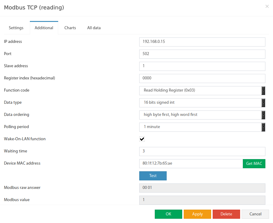
| Field Name | Description |
|---|---|
| IP Address | IP address of the Modbus TCP slave device in the network |
| Port | Modbus TCP port of the slave device (default: 502) |
| Slave Address | Slave address of the Modbus TCP device (usually 1) |
| Register Index | Start address of the Modbus register in hexadecimal notation, e.g. 0F4A |
| Function Code | Supported read functions:0x01 – Read Coil Status0x02 – Read Input Status0x03 – Read Holding Register0x04 – Read Input Register |
| Data Type | Defines data interpretation: 16-bit Signed Int · 16-bit Unsigned Int 32-bit Signed Int · 32-bit Unsigned Int · 32-bit IEEE Floating Point |
| Byte Order | Byte order in the Modbus response message:low byte first, low word firstlow byte first, high word firsthigh byte first, low word firsthigh byte first, high word first |
| Polling Interval | Time interval for querying the sensor value. Range: 10 seconds to 5 minutes. |
| Wake-on-LAN | Enables the Wake-on-LAN function. Only available if polling interval ≥ 1 minute. |
| Wait Time | Wait time until the remote device boots up after the WoL command. Range: 1–15 seconds. |
| Device MAC Address | MAC address of the target device for the Wake-on-LAN command. Can be retrieved automatically with „Get MAC“. |
Modbus TCP – Creating a Writing Element
⌄A virtual “Modbus TCP (Writing)” element enables the active writing of values to Modbus registers of external devices. This allows switch commands, setpoints or control commands to be transmitted via Modbus TCP. The writing element can also be used as a THEN task in logic plans.
- In the web interface, click the Add button in the Group Tree or System Tree menu.
- Select “Modbus TCP (Writing)” from the selection menu.
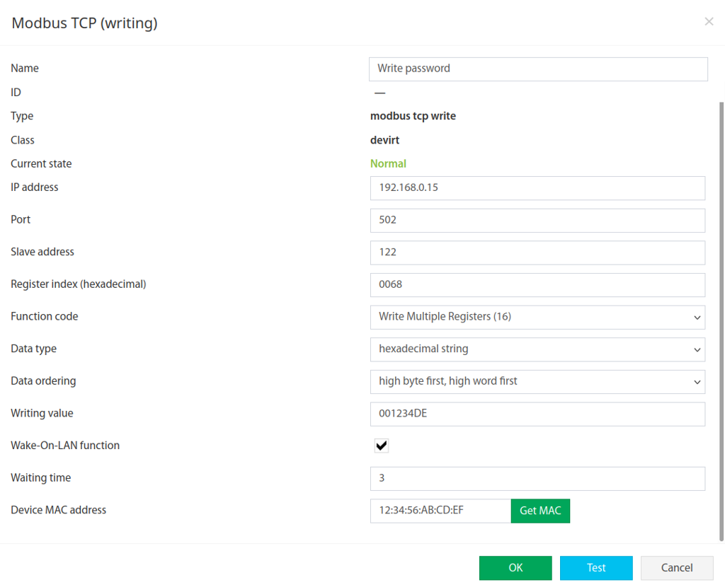
- The configuration form opens directly.
 🔍 Enlarge
| Field Name | Description |
|---|---|
| Name | Designation of the created element |
| IP Address | IP address of the Modbus TCP slave device |
| Port | Modbus TCP port (default: 502) |
| Slave Address | Slave address of the Modbus TCP device |
| Register Index | Register address in hexadecimal notation, e.g. 0F4A |
| Function Code | Supported write functions:0x05 – Write Single Coil0x06 – Write Single Register0x10 – Write Multiple Registers (16) |
| Data Type | 16-bit Signed/Unsigned Int · 32-bit Signed/Unsigned Int · 32-bit IEEE Floating Point · Hexadecimal String |
| Byte Order | Byte order of the Modbus message (same as in the reading element) |
| Write Value | The value that is written to the specified register (interpretation depends on the data type) |
| Wake-on-LAN | Enables Wake-on-LAN before the write operation |
| Wait Time | Wait time after WoL command. Range: 1–15 seconds. |
| Device MAC Address | MAC address of the target device for Wake-on-LAN |
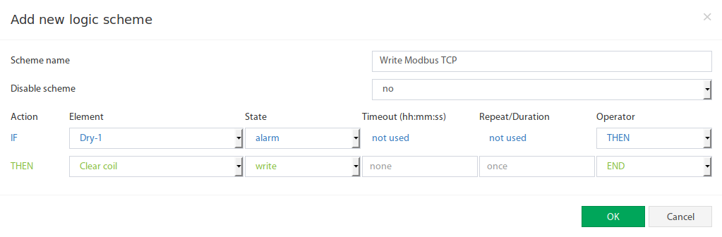 🔍 Enlarge
Practical Example: Integrating Elnet Energy Meter via Modbus TCP
⌄In this practical example, an energy meter from the manufacturer Elnet is integrated into a Didactum system via Modbus TCP. Elnet energy meters have multiple Modbus registers for voltage, current and other measured variables.
Elnet meters use decimal register indices in their documentation. However, the Didactum system expects hexadecimal register addresses. The conversion must therefore be done manually.
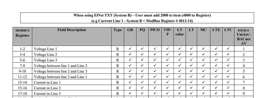 🔍 Enlarge
| Measured Variable | Register Index (HEX) |
|---|---|
| Voltage Phase L1 | 0001 |
| Voltage Phase L2 | 0003 |
| Voltage Phase L3 | 0005 |
| Voltage between L1 and L2 | 0007 |
| Voltage between L2 and L3 | 0009 |
| Voltage between L3 and L1 | 000B |
| Current Phase L1 | 000D |
| Current Phase L2 | 000F |
| Current Phase L3 | 0011 |
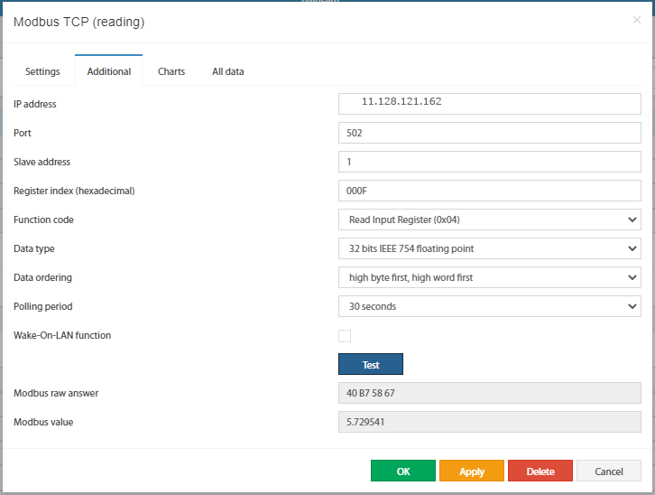 🔍 Enlarge
000F.
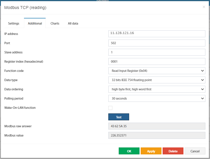 🔍 Enlarge
0001.
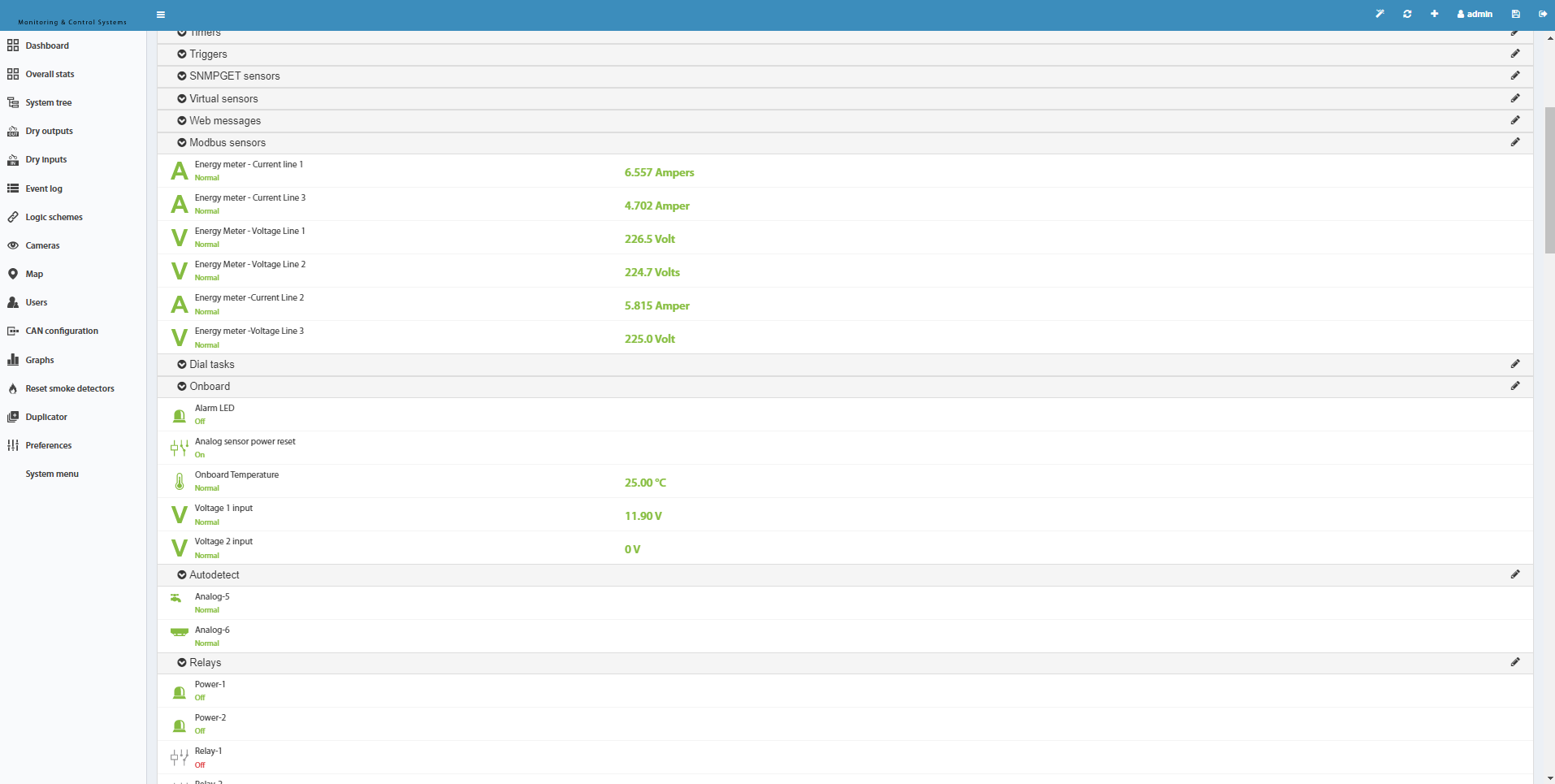 🔍 Enlarge
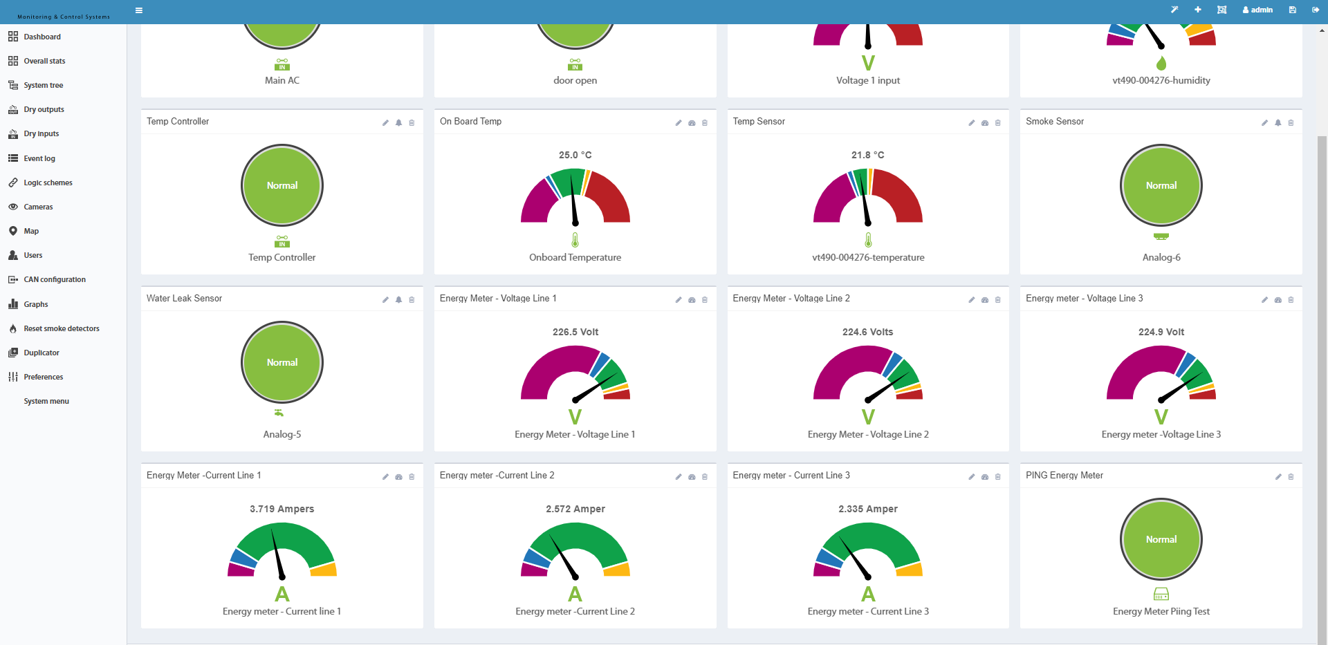 🔍 Enlarge
Modbus RTU – Activation & RS-485 Bus Setup
⌄A virtual “Modbus RTU” sensor element reads data from external devices via the Modbus RTU protocol (RS-485 bus). Typical applications are sensors, meters or control devices with an RS-485 interface.
Note: The expansion board supports only 1 stop bit.
- Connect the RS-485 bus according to the slave device documentation.
- In the Didactum web interface, navigate to Settings → Modbus RTU.
- Configure the bus according to the slave device documentation (baud rate, parity, stop bits).
- Enable Modbus RTU and save the settings.
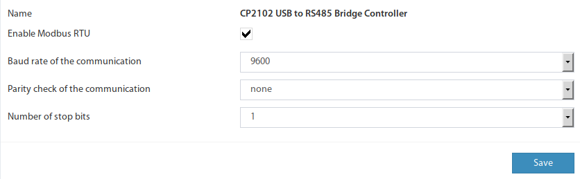 🔍 Enlarge
| Parameter | Typical Value | Note |
|---|---|---|
| Baud Rate | 9600 or 19200 | Must match the slave device |
| Parity | None | Check according to slave documentation |
| Data Bits | 8 | Standard for Modbus RTU |
| Stop Bits | 1 | Expansion board: only 1 stop bit! |
Modbus RTU – Creating a Reading Element
⌄After enabling Modbus RTU, you can create virtual reading elements that read measured values from the RS-485 bus and display them in the Didactum system.
- In the Didactum web interface, click the Add button in the Group Tree or System Tree.
- Select “Modbus RTU (Reading)” – a modal window will appear.
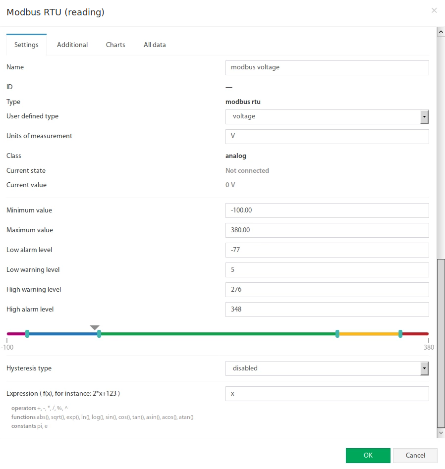
- Click on “Modbus RTU (Reading)” to open the configuration form.
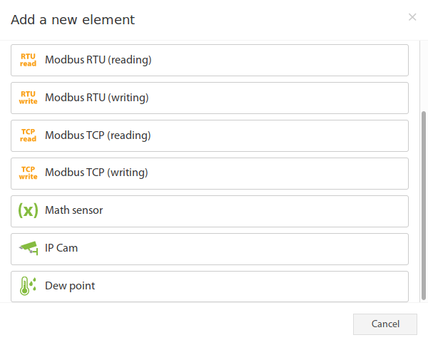 🔍 Enlarge
 🔍 Enlarge
| # | Field Name | Description |
|---|---|---|
| 1 | Name | Designation of the created element |
| 2 | Custom Type | Symbol in the system tree |
| 3 | Unit of Measurement | Display unit in the system tree (V, A, Hz ...) |
| 4 | Minimum Value | Lower measuring range – if value falls below: „Not connected“ state |
| 5 | Maximum Value | Upper measuring range – if value exceeds: „Not connected“ state |
| 6 | Alarm & Warning Thresholds | Alarm and warning limits |
| 7 | Hysteresis | Hysteresis setting |
| 8 | Expression | Calculation formula f(x), default: x. Decimal separator is a period (e.g. 3.14). Example: 0.1*x+0.5 |
| # | Field Name | Description |
|---|---|---|
| 1 | Slave Address | Slave address of the external Modbus RTU device (default: 1) |
| 2 | Register Index | Register address in hexadecimal notation, e.g. 0F4A |
| 3 | Function Code | 0x01 – Read Coil Status0x02 – Read Input Status0x03 – Read Holding Register0x04 – Read Input Register |
| 4 | Data Type | 16-bit Signed/Unsigned Int · 32-bit Signed/Unsigned Int · 32-bit IEEE Floating Point |
| 5 | Byte Order | Byte order in the Modbus response message (low/high byte first, low/high word first) |
| 6 | Polling Interval | Query time of the sensor value. Range: 10 seconds to 5 minutes. |
Modbus RTU – Creating a Writing Element
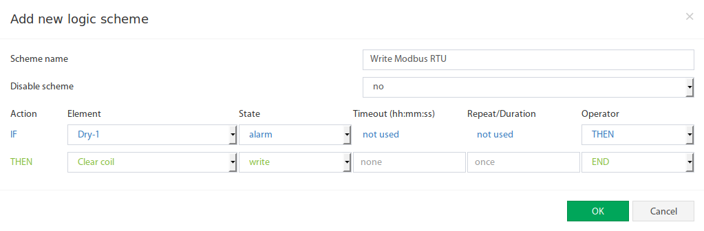
⌄The “Modbus RTU (Writing)” element allows active writing of values to Modbus RTU registers of external devices via the RS-485 bus. Like its TCP counterpart, it can be used as a THEN task in logic plans.
- In the web interface, click the Add button in the Group Tree or System Tree.
- Select “Modbus RTU (Writing)”.
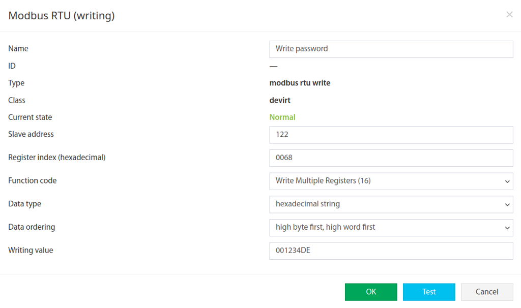
- The configuration form opens directly.
 🔍 Enlarge
| # | Field Name | Description |
|---|---|---|
| 1 | Name | Designation of the element |
| 2 | Slave Address | Slave address of the external Modbus RTU device |
| 3 | Register Index | Register address in hexadecimal notation, e.g. 0F4A |
| 4 | Function Code | 0x05 – Write Single Coil0x06 – Write Single Register |
| 5 | Write Value | Integer decimal value to be written to the specified register |
 🔍 Enlarge
Tested Sensors & Configuration Reference
⌄The following table contains verified Modbus configurations for devices that have been successfully tested with Didactum systems. The values can be directly copied into the respective Modbus elements.
1 by the manufacturer, but can be changed manually on the device. Please check the setting on the slave device.| Manufacturer | Device | Description | Measured Value | Slave Address | Register Index (HEX) | Function Code | Data Type | Byte Order | Polling Interval |
|---|---|---|---|---|---|---|---|---|---|
| Circutor | CVM-C10 Series | Power Analyzer, Panel | Voltage (V) | 1 |
0000 |
Read Input Register (0x04) |
32-bit Unsigned Int | high byte first, high word first | 10 seconds |
| Frequency (Hz) | 1 |
003C |
Read Input Register (0x04) |
32-bit Unsigned Int | high byte first, high word first | 10 seconds | |||
| Eastron | SDM220 Series | Energy Meter | Voltage (V) | 1 |
0000 |
Read Input Register (0x04) |
32-bit IEEE 754 Float | high byte first, high word first | 10 seconds |
| Active Power (Watt) | 1 |
000C |
Read Input Register (0x04) |
32-bit IEEE 754 Float | high byte first, high word first | 10 seconds | |||
| Frequency (Hz) | 1 |
0046 |
Read Input Register (0x04) |
32-bit IEEE 754 Float | high byte first, high word first | 10 seconds |
- Check register addresses: Manufacturers often specify registers in decimal – Didactum requires hexadecimal notation. Online converters help with the conversion (e.g. Dec 60 = Hex
003C). - Determine data type: Check the Modbus manual of the slave device for the data format used (16-bit, 32-bit, Float ...).
- Test byte order: If the read value appears incorrect, try a different byte order. The most common combination is
high byte first, high word first. - Test connection: Always use the Test button before saving the element. The raw data helps with troubleshooting.
- Polling interval: For rapidly changing values (e.g. current) choose the minimum of 10 seconds. For rarely changing values, a larger interval can reduce network load.