


Didactum Monitoring Systems
SNMP Configuration & MIB Reference
Complete guide to monitoring and controlling your Didactum unit via SNMP: enable agent, read sensors, set up logic & traps, switch relays.
Table of Contents
- Introduction: What is SNMP?
- Overview: Architecture & MIB Structure
- Enable SNMP Agent & MIB File
- System Elements Overview
- Logic (Automatic Control)
- Discrete Sensors
- How It Works (Agent & Sub-Agent)
- Analog Sensors
- Save Settings (Flash)
- Trap Notifications
- Relays & Outputs (SNMP)
- SNMP Configuration Examples
Introduction: What is SNMP?
▼SNMP (Simple Network Management Protocol) is an application-layer protocol for managing devices in TCP/IP networks. It usually runs over UDP on the transport layer and has been used for years across industries for central infrastructure monitoring.
Every Didactum monitoring unit has a built-in SNMP agent and can therefore be controlled and read by a higher-level network management station (the so-called "Manager").
The SNMP agent in Didactum devices is compatible with the managed object model MIB-II (RFC 1213). The Management Information Base (MIB) – the model of the object managed in network management – is defined according to the ASN.1 standard.
Didactum devices also support Trap Protocol Data Units (PDU). A Trap PDU is a notification that the device sends to the network management station as soon as relevant states change during operation. After the station has received the trap, it can send a query back to the device to determine the exact cause of the message.
Structure of this manual
The following chapters will guide you step by step through enabling SNMP, the structure of the MIB database, and the evaluation and control of sensors, relays, logic circuits and traps on your Didactum unit.
Overview: Architecture & MIB Structure
▼Versions
| Component | Version |
|---|---|
| SNMP Agent | Net-SNMP from version 5.7.1 |
| Didactum Sub-Agent | Software from version 2.0.2 |
Compatibility
Current Didactum devices support SNMP in versions 1, 2c and 3.
The MIB Database
All details of the monitoring system are located in the MIB branch .iso.org.dod.internet.private.enterprises.didactum with the OID .1.3.6.1.4.1.39052.
Didactum for historical and technical compatibility reasons. This is normal and has no impact on functionality or support.The MIB file can be downloaded via the web interface of any Didactum unit: Web Interface → Settings → SNMP → "Download MIB File".
Available Tables in the MIB Tree
| MIB Branch | Contained Tables |
|---|---|
| ctlUnit System Unit | ctlUnitModulesTable – System modules · ctlUnitGroupsTable – Groups · ctlUnitElementsTable – all elements · ctlUnitLogicsTable – Logic circuits · ctlUnitTrapNotification – Trap notification · ctlUnitSaveToFlash – Save to flash memory |
| ctlNotifiers Notifications | ctlNotifiersMailersTable – E-Mail · ctlNotifiersTrapsTable – SNMP Traps · ctlNotifiersSMSsTable – SMS |
| ctlVirtualDevices Virtual Devices | ctlVirtualDevicesTimersTable – Timers · ctlVirtualDevicesPingsTable – Ping sensors · ctlVirtualDevicesTriggersTable – Triggers · ctlVirtualDevicesSnmpgetsTable – virtual SNMP Get sensors |
| ctlHardwareDevices Hardware Devices | ctlHardwareDevicesCamerasTable – USB and IP cameras |
| ctlInternalSensors Internal Sensors | ctlInternalSensorsDiscretsTable – discrete sensors · ctlInternalSensorsAnalogsTable – analog sensors · ctlInternalSensorsOutletsTable – Relays/Outputs |
| ctlCANSensors CAN-Bus Sensors | ctlCANSensorsDiscretsTable · ctlCANSensorsAnalogsTable · ctlCANSensorsOutletsTable |
| ctlRsSensors Sensors on the serial interface | ctlRsSensorsDiscretsTable · ctlRsSensorsAnalogsTable · ctlRsSensorsOutletsTable |
SNMP Agent Activation & MIB File
▼Set Communities
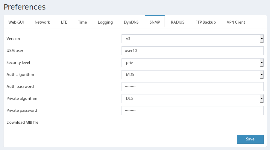
The SNMP community settings can be found in the web interface under Settings → SNMP, in the fields "Community for SNMP (read only)" and "Community for SNMP (write)".
Download MIB File
The MIB file is also available under Settings → SNMP via the link "Download MIB File".
 🔍 Enlarge
Overview of the "Community for Read/Write" fields, the link to download the MIB file, and the checkbox to enable SNMP – all centrally located under Settings → SNMP.
Enable SNMP Agent (Versions & Security)
Current Didactum devices support SNMP versions 1, 2c and 3. For SNMP version 3, additional advanced security settings are available.
~!@#$%^&()_=*-+{}[]:;<>"|/| Version | Option | Value / Note |
|---|---|---|
| v1 / v2c | Read Community | public (default) |
| Write Community | private (default) | |
| v3 | USM User | freely selectable |
| Security Level | "No Auth, no Priv" / "Auth, no Priv" / "Auth, Priv" | |
| Authentication Algorithm | MD5 or SHA (only with "Auth") | |
| Authentication Password | min. 8 characters | |
| Privacy Algorithm | DES or AES (only with "Priv") | |
| Privacy Password | min. 8 characters |
Activate SNMP on the Unit
- Open the web interface of your Didactum unit.
- Navigate to the main menu Settings → SNMP.
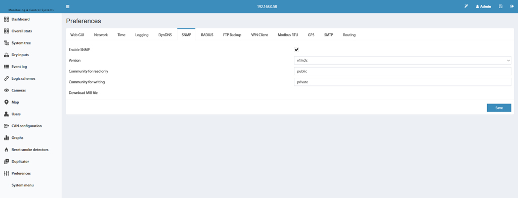
- Check the option "Enable SNMP".
- Select the desired SNMP version (v1/v2c or v3) and enter the appropriate credentials.
- Click "Save".
 🔍 Enlarge
After checking the "Enable SNMP" box and selecting the appropriate version, all SNMP functions of the unit are immediately available after saving.
Check Connection to the MIB File Manager
Example: How to check if the MIB file was correctly integrated:
System Elements Overview
▼The monitoring system of a Didactum unit can include the following types of elements:
- Analog Sensors
- Discrete Sensors
- Virtual Sensors (Elements)
- Notifications
- System Units
All available elements of the system are summarized in the table ctlAllElementsTable.
Example: Reading Available System Elements
Example: Retrieve Value of an Element (ID = 201002)
7 in the OID stands for the table column to which the sensor value is assigned; 201002 is the unique sensor ID.Example: Change Name of an Element (ID = 102003)
Logic (Automatic Control)
▼Logic is the mechanism for automatic control of your Didactum unit: It links sensor states with actions such as switching a relay or triggering a trap.
Syntax of Logic Description
A logic is described by the following string:
| Parameter | Meaning |
|---|---|
SENSORID | Unique ID of the triggering sensor |
OLDSTATE-NEWSTATE | State codes where the transition fulfills the condition (both values identical) |
OPERATOR | Linking code for multiple conditions |
SENSORID1 | ID of the element (e.g. relay) whose state should be changed |
TIMEOUT | Delay in seconds before the action is executed |
NEWSTATE2 | Target state of the element |
OPERATOR2 | Symbol „+" |
State Codes
| State | Code |
|---|---|
| normal | 1 |
| low | 2 |
| warning | 3 |
| alarm | 4 |
| on | 5 |
| off | 6 |
| not connected | 7 |
| pulse | 8 |
Operator Codes
| Operator | Symbol |
|---|---|
| AND | + |
| OR | | |
Manage Logic
- A new logic is created via the field
ctlLogicRowStatus: Set it to stateCreateAndWait(5)to create a new entry inctlLogicsTable. - Then assign a name in the field
ctlLogicNameand the logic description in the fieldctlLogicDescription. - After entering the description, the logic becomes active – recognizable by the value
active(1)in the fieldctlLogicRowStatus. - To temporarily disable, set
ctlLogicDisableto the desired interval in seconds; to reactivate, set it to0. - To delete, set
ctlLogicRowStatusto statedestroy(6).
Example: Create, Check, Disable and Delete Logic
Discrete Sensors
▼Discrete output sensors of your Didactum unit are stored in the following sub-branches depending on their physical connection:
ctlInternalSensors– internal main sensors →ctlInternalSensorsDiscretsTablectlCANSensors– sensors on the CAN bus →ctlCANSensorsDiscretsTablectlRsSensors– sensors on the serial interface →ctlRsSensorsDiscretsTable
Example: Reading Discrete Sensors
The position of a sensor in the system is determined by the module ID (Module) in which it is physically installed, and the port number on the module (Num).
Possible States
| State | Meaning |
|---|---|
normal | Sensor reports no alarm |
alarm | Sensor has triggered |
not connected | Sensor not connected |
The measured raw values are in the Value field and can take the value 1 or 0. If required, the logic can be inverted by setting the Reverse field to 1 (default: 0).
Example: Set Up Inversion of a Sensor (ID = 101004)
Reset Smoke Detector
For smoke detectors on the CAN bus (sensor model VT460), a reset of the alarm state is available via SNMP-SET: Write the string value reset smoke (without quotes) to the OID .1.3.6.1.4.1.39052.6.1.1.11 (ctlCANSensorsDiscretSpecific) with the respective sensor ID.
Functionality (Agent & Sub-Agent)
▼When a Didactum unit is booted, the SNMP agent is started first, followed by the sub-agent that provides the device-specific functionality.
After startup and the connection between agent and sub-agent, the agent processes incoming requests from the network management station (Manager) – so-called SNMP PDUs (Protocol Data Units) such as Get-PDU, GetNext-PDU or Set-PDU – and generates a corresponding response or a Trap-PDU.
Trap PDUs are dynamically defined in the monitoring system: The Logic links trap messages with specific system events.
Analog Sensors
▼Analog sensors of Didactum devices have analog inputs as well as analog or discrete outputs. If an analog sensor is not connected or undefined, it is in the state "not connected".
Analog sensors are also stored in the following sub-branches depending on their physical connection:
ctlInternalSensors→ctlInternalSensorsAnalogsTablectlCANSensors→ctlCANSensorsAnalogsTablectlRsSensors→ctlRsSensorsAnalogsTable
Example: Reading Analog Sensors
The position of a sensor in the system is also determined here by the module ID (Module) and the port number on the module (Num).
Possible States & Thresholds
An analog output sensor can assume the following states depending on the threshold values ctlAnalogLowAlarm, ctlAnalogLowWarning, ctlAnalogHighWarning and ctlAnalogHighAlarm:
| State | Meaning |
|---|---|
normal | Measured value is above "Low" but below "Warning"/"Alarm" |
low alarm | Measured value is below the "LowAlarm" threshold |
low warning | Measured value is above "LowAlarm" but below "LowWarning" |
high warning | Measured value is above "HighWarning" but below "HighAlarm" |
high alarm | Measured value is above the "HighAlarm" threshold |
Conversion for Voltage Sensors
The fields ctlAnalogAT0 (default "1.0") and ctlAnalogAT75 (default "0.0") apply exclusively to voltage sensors and define the coefficients for converting the measured value according to the following formula:
Conversion for Current Sensors (4–20 mA)
The field ctlAnalogExpression (default "x") applies exclusively to current sensors and defines the expression for converting the measured value:
With the default setting, the displayed value corresponds exactly to the unchanged measured value. The supported operators are + − / * % (Modulo) and ^ (power) as well as the following functions:
| Function | Meaning |
|---|---|
abs | Absolute value |
sqrt | Square root |
exp | Exponential function |
ln | Natural logarithm |
log | Logarithm |
sin / cos / tan | Trigonometric functions |
asin / acos / atan | Inverse functions |
Example: Set Thresholds (Element ID = 22)
Save Settings (Flash)
▼Every Didactum unit uses a NAND flash memory as rewritable system memory. This memory has only a limited number of write cycles – therefore, sensor settings changed during operation must be explicitly saved to the flash memory by the user.
The special resource ctlUnitSaveToFlash is used to save sensor settings via SNMP. Setting any value other than "0" here saves the current settings to the flash memory.
ctlUnitSaveToFlash automatically resets to 0. Otherwise, the field returns an error code indicating the cause of the save failure.Example: Save Settings to Flash Memory
Trap Notifications
▼A Trap is a notification element that sends a trap message (Trap PDU) from the monitoring system (agent) of your Didactum unit to the network management station (SNMP manager). SNMP trap messages of versions 1, 2c and 3 are supported.
Manage Traps
Trap elements can only be created, configured and deleted via the web interface – pure SNMP management is not provided for this.
Structure of the Trap Message
When sending a trap message, a description line is automatically generated, for example:
Here trap_1 stands for the name and 602001 for the unique ID of the trap element. The name can be changed via the table ctlNotifiersTrapsTable or directly in the web interface.
Variables Passed in the Message
| Variable | Description |
|---|---|
.1 | Description of the triggered logic circuit |
.2 | Measured values of the sensors in the logic circuit |
.3 | Reaction time of the logic circuit |
.4 | Name of the logic circuit |
.5 | Name of the sensor whose state triggered the logic |
.6 | State of the triggering sensor |
.7 | Measured value or logic level |
.8 | ID of the triggering sensor |
.20 | ID of the SNMP trap |
.21 | Name of the SNMP trap |
Relays & Outputs (SNMP)
▼The output elements (relays/outputs) of your Didactum unit are stored in the following sub-branches depending on their physical connection:
ctlInternalSensors→ctlInternalSensorsOutletsTablectlCANSensors→ctlCANSensorsOutletsTablectlRsSensors→ctlRsSensorsOutletsTable
Example: Reading Available Outputs
The position of an output in the system is also determined here by the module ID (Module) and the port number on the module (Num).
Possible States
| State | Meaning |
|---|---|
on | switched on |
off | switched off |
pulse | Pulse switching for a defined duration |
The initial state after booting is defined in the Initial field. Control itself is done via the Value field; the pulse duration in seconds is defined in the Pulse field.
Example: Send 5-Second Pulse to Relay (ID = 102003)
SNMP Configuration Examples
▼This chapter shows how to connect your Didactum unit via SNMP in just a few steps using a typical MIB browser.
Step 1 – Download MIB File
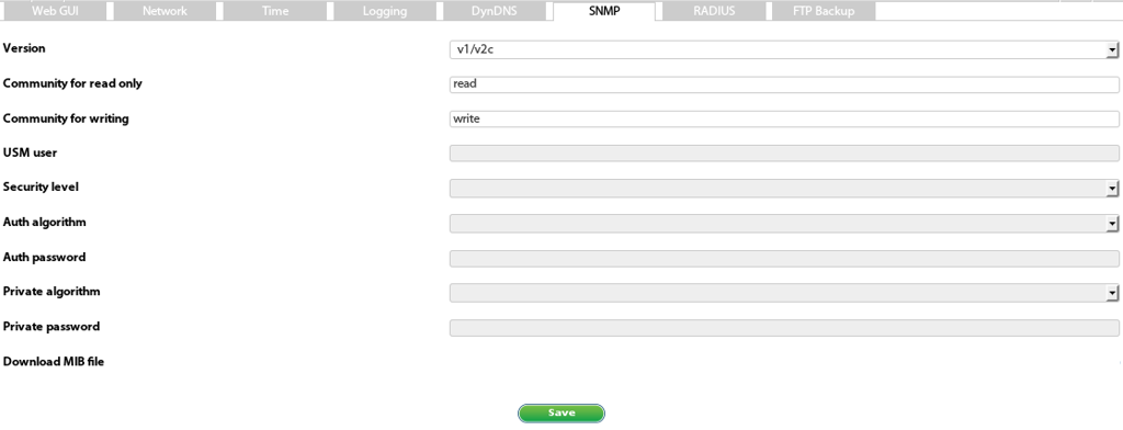
The MIB file is available in the web interface under Settings → SNMP → "Download MIB File".
 🔍 Enlarge
Download the file and then import it into your preferred SNMP manager or MIB browser.
Step 2 – Load MIB File into the Manager
- Load the downloaded MIB file into your SNMP manager or MIB browser.
- Enter the same community names for read and write that you previously set on the Didactum unit.
- Enter the correct IP address, port and SNMP version of the unit in the manager (for SNMP v3 also the access passwords).
- Check the connection and test-read the content of the sensor and element fields.
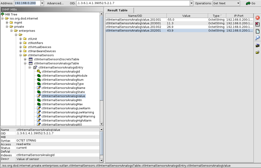
Step 3 – Sensor Values Tree in the MIB Browser
 🔍 Enlarge
This is how the branch of analog sensor values appears in a typical MIB browser after importing the Didactum MIB file.
OID Examples for Direct Access
If you want to read a specific sensor field directly, simply append the respective sensor ID to the appropriate base OID:
.1.3.6.1.4.1.39052.5.2.1.7.201001– Measured value of the analog temperature sensor with ID 201001.1.3.6.1.4.1.39052.5.2.1.5.201001– Assigned name of the same temperature sensor.1.3.6.1.4.1.39052.5.1.1.7.101003– Value of the discrete dry contact input with ID 101003.1.3.6.1.4.1.39052.5.1.1.5.101003– Assigned name of the same dry contact input