


Didactum Monitoring Systems
Advanced Configuration & Features
Complete guide to dry contacts, relays, timers, charts, configuration of virtual elements, cameras and more – for all Didactum devices.
Table of Contents
- Dry Contacts – Configuration Area
- Switching Relays (NC/NO) & Outputs
- Create Timer / Schedule
- Using Timers – Practical Examples
- Charts / Graph Panel
- Configure 12V Relays
- Create Virtual Math Element
- Math Element for Detecting Digital States
- Configure Cameras & Camera Panel
- Video Notifications via USB Webcam
Dry Contacts – Configuration Area
▼The dry contacts area is used to control and configure internal dry contact inputs as well as expansion modules on Didactum monitoring devices. For internal contacts, the behavior type (normal or inverted) and the input type can be defined.
Using Groups
With a large number of dry contacts, it can be useful to create a group and combine multiple contacts within it. A single event (e.g. a notification) is then triggered as soon as any element in the group triggers an alarm.
 🔍 Enlarge
The input type only affects the icon in the interface. Available types: airflow, door, motion, smoke, vibration, water or no special type. For dry contacts on the CAN bus, the alarm hold duration can also be set.
 🔍 Enlarge
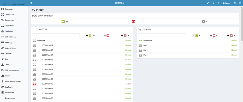
The overall view shows all configured dry contact inputs. The button in the top left corner can be used to start a logic circuit wizard.
Create Logic Circuit for Dry Contacts
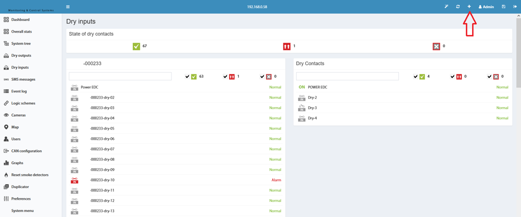
- Click the "+" button in the top left corner of the dry contact area to start the wizard.
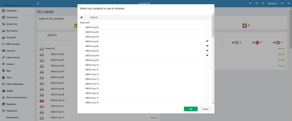
- In the first step, select the desired dry contacts for the logic circuit.
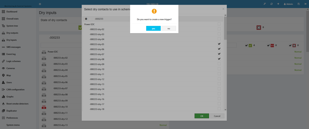
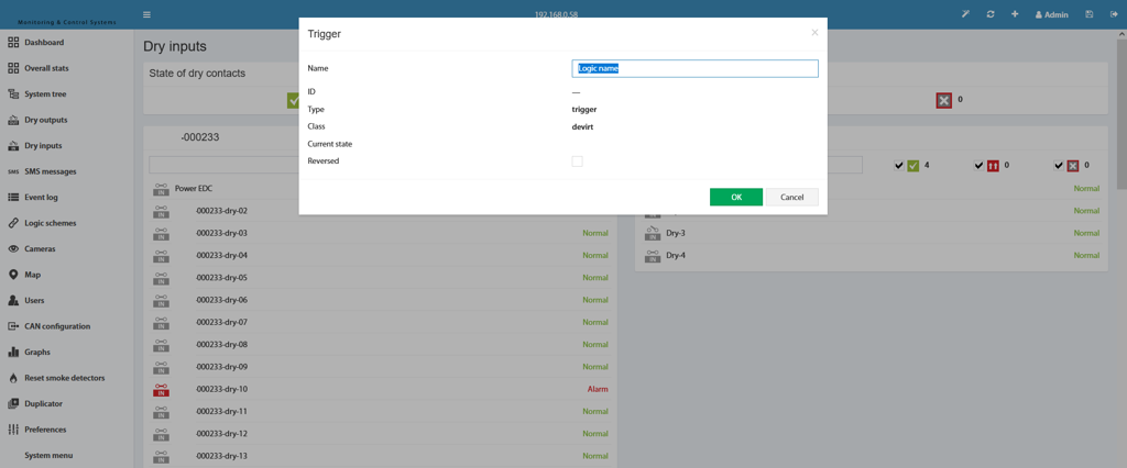
- After clicking "OK", the creation of a trigger is offered – this step is optional.
- Finally, edit the logic circuit and confirm with "OK".
 🔍 Enlarge
In the first wizard step, the dry contacts that should be part of the logic circuit are selected.
 🔍 Enlarge
The trigger is optional. Without a trigger, only already existing elements can be used in the THEN part of the logic circuit.
 🔍 Enlarge
In the last step, the circuit is edited and saved with "OK".
Switching Relays (NC/NO) & Outputs
▼Switching relays and outputs is done via the system tree in the web interface of all Didactum devices. Each relay can be configured individually and switched time-controlled using the pulse function.
 🔍 Enlarge
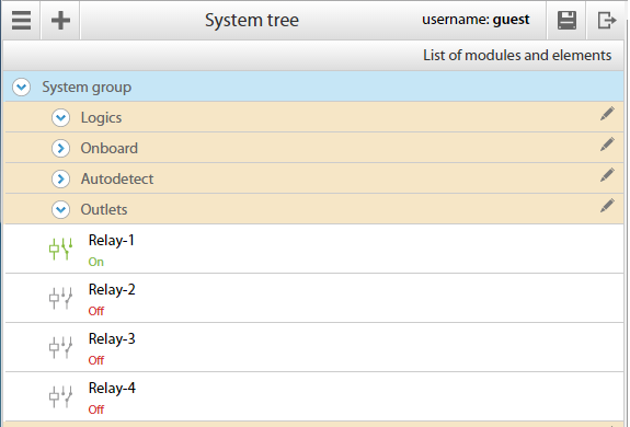
Go to Main Menu → System Tree, select the desired Relay element and click on it. A dialog window with the properties will open.
 🔍 Enlarge
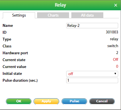
In the properties window you can define name, group, hardware port, initial state and the new state including pulse duration.
Relay Parameters at a Glance
| # | Parameter | Description |
|---|---|---|
| 1 | Name | Default „Relay-#", freely changeable. |
| 2 | Group | Select group for visual representation in the group tree. |
| 3 | Hardware Port | Port 1 = Relay 1 / Output 1 etc. |
| 4 | Current State | Shows the current switching state of the relay. |
| 5 | Current Value | „0" = off, „1" = on. |
| 6 | Initial State | „off" = switched off at system start; „on" = switched on at system start. |
| 7 | New State | „Do not change" = no pulse; „Pulse" = switch relay to the opposite state for the pulse duration. |
| 8 | Pulse Duration | Specified in seconds; minimum 1 second. |
Switching Outputs
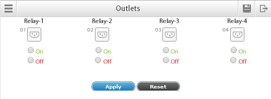
For devices with controllable outputs (e.g. power strips), the Main Menu → Outputs area is available in the main menu.
 🔍 Enlarge
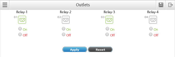
Select the desired outputs and click "Apply". Switched-on outputs are highlighted in green. The pulse function always reverses the state of the relay to the opposite state.
 🔍 Enlarge
Relay-1 (Output-1) and Relay-3 (Output-2) are switched on (green). The other outputs are switched off. Individual control of single outputs is possible via Groups / System Tree → Relays.
Create Timer / Schedule
▼With the timer function, you can schedule events in your Didactum monitoring system on a time-controlled basis. A timer works like a schedule and can be activated once, weekly, or monthly. When triggered, the timer switches to the Alarm state; when it expires, it returns to the Normal state.
Create a Timer
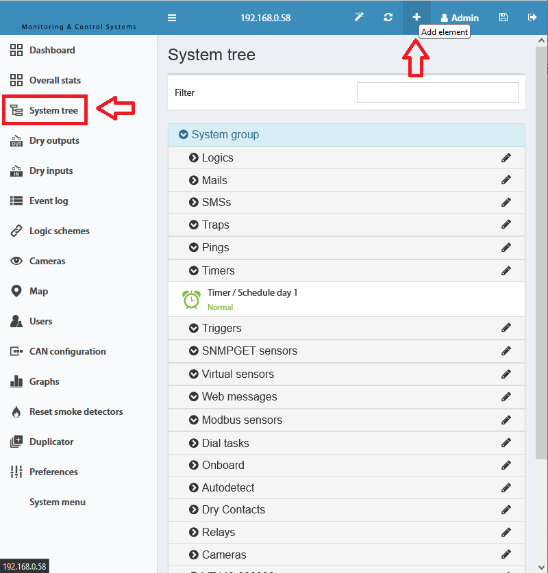
To create a timer, press the "+" button in the group or system tree and select "Timer".
 🔍 Enlarge
Clicking the "+" button in the group or system tree opens a selection menu. Choose "Timer" to open the configuration window.
 🔍 Enlarge
Define name, operating mode and start/end times. After clicking "OK", the timer automatically switches to Alarm mode at the specified start time.
Timer Options at a Glance
| Parameter | Mode | Description |
|---|---|---|
| Name | – | Freely selectable name for easy differentiation of multiple timers. |
| ID | – | System-assigned ID of the virtual timer element. |
| Type | – | Virtual element of type "Timer". |
| Device Time | – | Currently displayed system time of the device. |
| Operating Mode | one-time | One-time event at the specified time. |
| weekly | Weekly repetition on the selected days of the week. | |
| monthly | Monthly repetition on the selected days (1–31). | |
| Schedule | Extended weekly schedule: individual times possible for each day of the week. |
One-Time Timer
 🔍 Enlarge
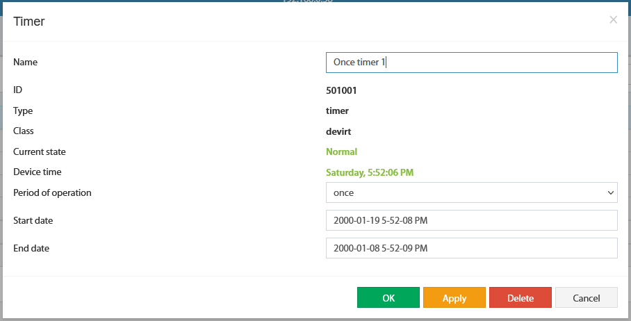
Start date and time: exact time at which the timer switches to Alarm mode (Year/Month/Day Hour/Minute/Second). End date: time at which the timer returns to Normal mode.
Weekly Timer
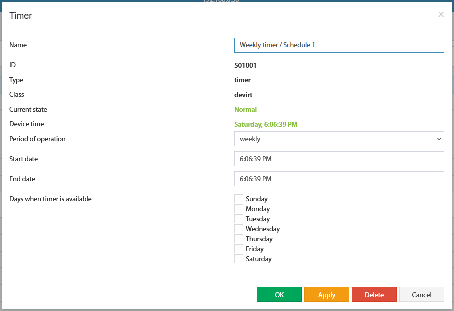 🔍 Enlarge
Specify start time, end time (hour/minute/second each) and the days of the week on which the timer should be active. All 7 days (Sun–Sat) can be activated independently.
Monthly Timer
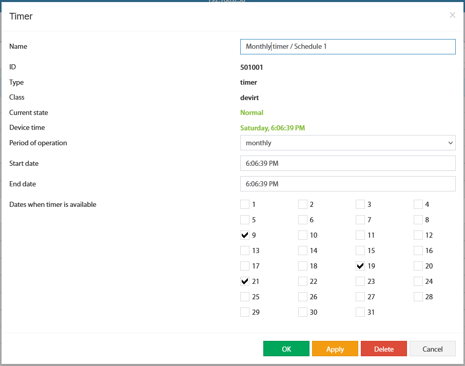 🔍 Enlarge
Specify start time, end time and the days of the month (1–31) on which the timer should be activated.
Schedule Timer
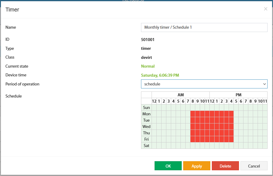 🔍 Enlarge
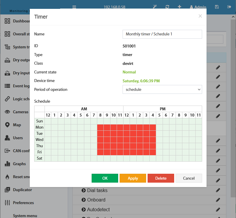
In schedule mode, you can individually activate specific hours for each day of the week (marked in red = active hours). This allows different times for weekdays and weekends, for example.
Using Timers – Practical Examples
▼The timer function can be used in many ways – from access control and motion monitoring to automatic restarts. Here are typical application examples for your Didactum system.
Example 1: Weekly Mode – Door Lock Control
Task: Open door lock (Relay Output 1) according to the following schedule: Mon–Fri 10–17, Sat 10–13. Two timers are created for this:
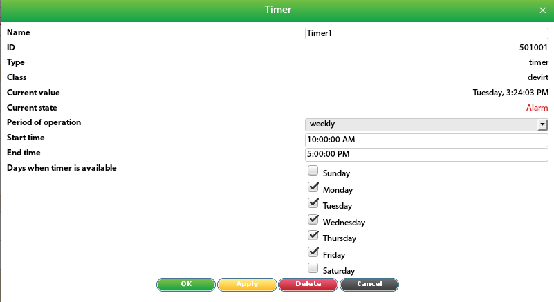 🔍 Enlarge
Weekly timer for Monday to Friday, 10:00–17:00. This timer controls the opening of the door lock on weekdays.
 🔍 Enlarge
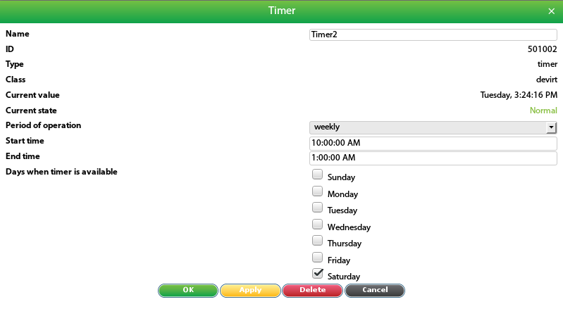
Weekly timer only for Saturday, 10:00–13:00. The logic circuits for door opening and door closing are then linked to the respective timers.
 🔍 Enlarge
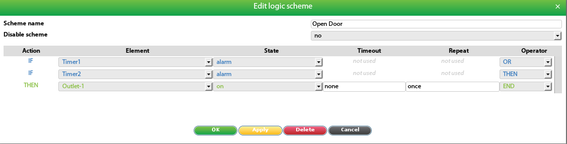
When the timer switches to Alarm state (IF), the relay for door opening is switched on (THEN). If the door lock is unlocked with a voltage pulse, the pulse function must be set accordingly.
 🔍 Enlarge
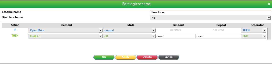
When the timer returns to Normal state (IF), the relay is switched off (THEN) to close the door.
Example 2: Schedule Mode – Motion Monitoring
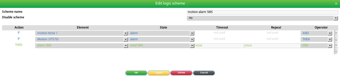
Task: Motion detector (PIR sensor) should only be active at certain times: Mon–Fri at night from 18:00–7:00, Sat+Sun all day. An SMS should be sent in case of motion alarm.
 🔍 Enlarge
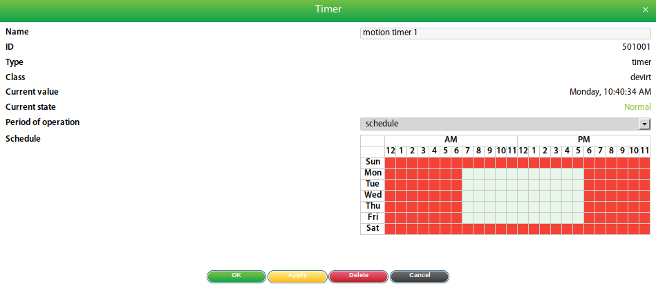
Mon–Fri: Hours 18–7 active (night mode). Sat + Sun: All hours active. The timer controls whether a motion alarm triggers a notification.
 🔍 Enlarge
IF motion detector in Alarm state AND timer active → THEN send SMS notification. This prevents false alarms outside the monitoring times.
Example 3: Automatic Restart (Sanitary Reboot)
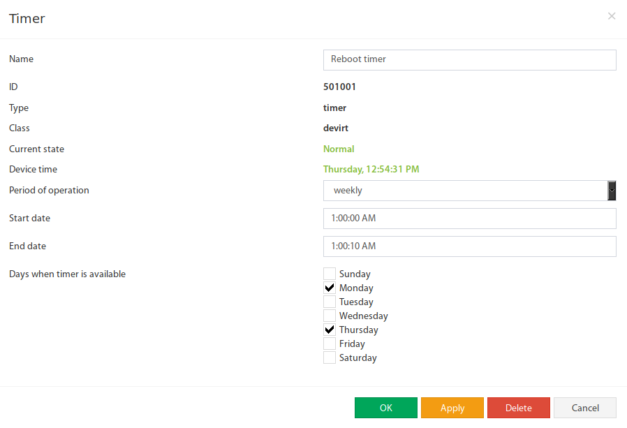
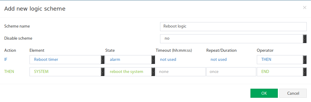
Useful for remote devices with no direct access: The device is automatically restarted twice a week (e.g. Mon and Thu).
 🔍 Enlarge
Weekly timer: Start and end time only a few seconds apart, active days: Monday and Thursday. This triggers the restart weekly.
 🔍 Enlarge
IF timer in Alarm state → THEN system restart. Note: The system is protected by a lock – no restart in the first 15 minutes after startup.
Charts / Graph Panel
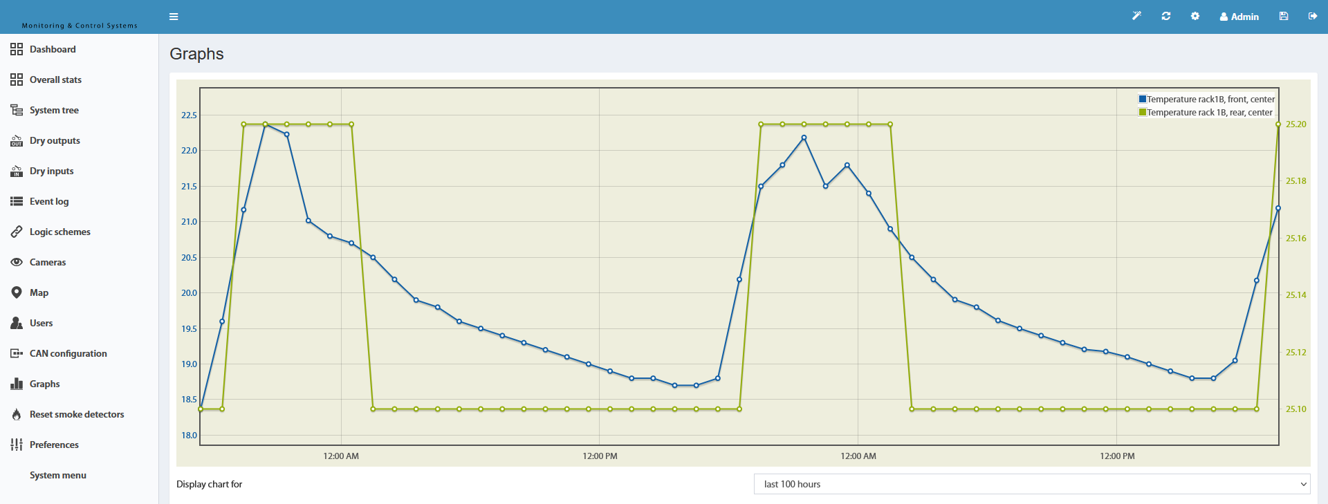
▼The graph panel enables comparative analysis of sensor value trends. Multiple sensors can be displayed simultaneously in one chart – ideal for comparing voltage, temperature and humidity over the same period on your Didactum device.
 🔍 Enlarge
The graph panel is used for historical analysis and comparison of sensor values. Temperature, voltage, humidity and other measured values can be displayed simultaneously.
Add Sensors to the Chart
| Step | Action | Description |
|---|---|---|
| 1 | Click gear icon | Click the gear icon on the right side of the top bar to open a selection window. |
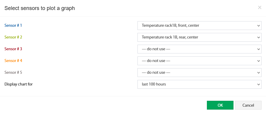
| 2 | Select sensors | Select the desired sensors for the chart and click "OK". |
| 3 | Choose time range | Set the desired display period for the chart. |
 🔍 Enlarge
The gear icon in the top right of the graph panel opens the sensor selection.
 🔍 Enlarge
From the list of available sensors, select those that should be displayed in the chart and confirm with "OK".
Configure 12V Relays
▼Didactum monitoring devices feature 12V-DC outputs for connecting alarm lights, strobes, locks, and other 12V devices. Configuration is done directly in the web interface of your Didactum system.
Step-by-Step Configuration
- Log in to the web interface.
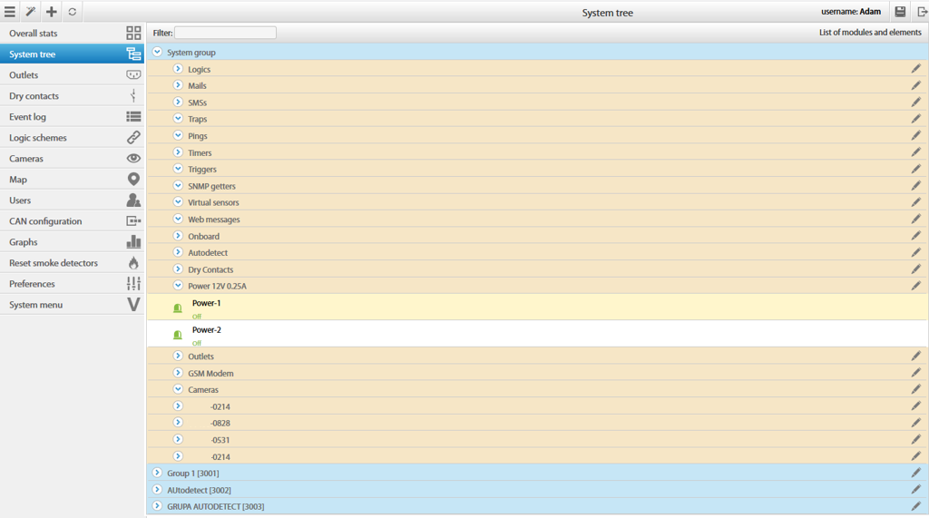
- Navigate to the 12V relay: System Tree → Power 12V 0.25A → Select relay
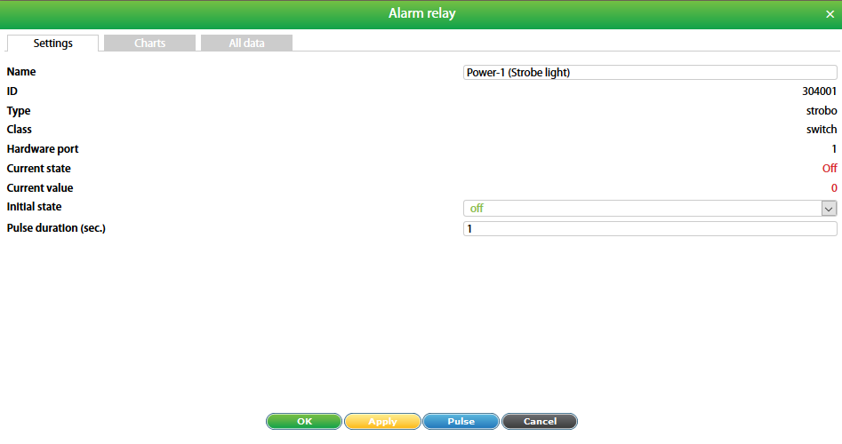
- In the configuration window, rename the relay, set the initial state, and enter the pulse duration in seconds.
 🔍 Enlarge
Navigate in the system tree to Power 12V 0.25A and select the desired relay (default Power-1 and Power-2).
 🔍 Enlarge
Assign a name, set the initial state (On/Off at system startup) and enter the pulse duration in seconds for time-controlled actions.
Compatible 12V Devices
| Device | Purpose |
|---|---|
| Alarm light / Signal device | Visual alarm in case of faults |
| Strobe light | Flashing warning light for critical alarms |
| Door lock | Electric lock for access control |
| Relay expansion | Expansion of switching contacts via external relays |
Create Virtual Math Element
▼The virtual "Math Sensor" allows the calculation of values from any sensor data using mathematical formulas. Example: The volume of a tank with an irregular shape can be calculated using a formula and the value of a level sensor. This function is available on all Didactum monitoring systems.
Create Math Element
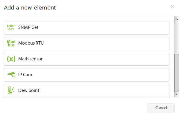
Press the "+" button in the group or system tree and select "Math Sensor".
 🔍 Enlarge
Via "+" in the system tree → select "Math Sensor". A configuration window with two tabs (General and Additional) opens.
 🔍 Enlarge
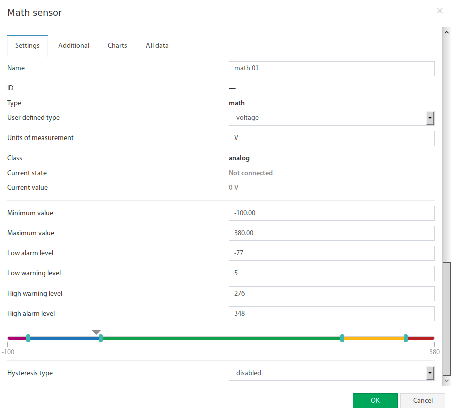
Define name, display type (symbol), unit of measurement, minimum and maximum value as well as alarm and warning thresholds.
Fields in the Configuration Window (General)
| # | Field | Description |
|---|---|---|
| 1 | Name | Name of the created element. |
| 2 | Custom Type | Defines the symbol in the system tree. |
| 3 | Unit | The unit in which the value is displayed. |
| 4 | Minimum Value | Lower measurement range limit; falling below switches the sensor to "Not connected" state. |
| 5 | Maximum Value | Upper measurement range limit; exceeding switches the sensor to "Not connected" state. |
| 6 | Alarm and Warning Levels | Defines alarm and warning thresholds like regular sensors. |
| 7 | Hysteresis | Setting of hysteresis for stable states. |
 🔍 Enlarge
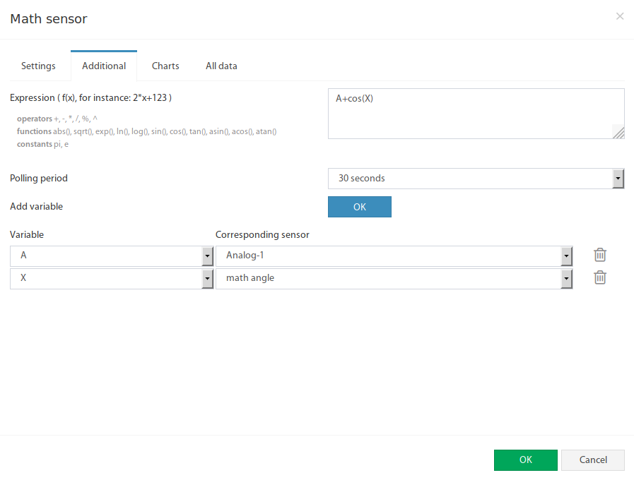
In the "Additional" tab, the formula expression, query interval and the variables (A–Z) with the corresponding sensors are configured.
Fields in the Additional Tab
| # | Field | Description |
|---|---|---|
| 1 | Expression | Mathematical formula f(x). Allowed characters: ( ), operators: + - * / % ^, functions: abs, sqrt, exp, ln, log, sin, cos, tan, asin, acos, atan, constants: pi, e. Decimal separator: period. Example: 0.1*x+0.5 |
| 2 | Query Interval | Update time of the sensor value. |
| 3 | Add Variable | Add new variable to the formula. |
| 4 | Variable | Unique variable name A–Z (uppercase letters, no duplicates). |
| 5 | Associated Sensor | The sensor whose value is used in the calculation. |
e is the mathematical constant Euler's number (≈ 2.71828); always use uppercase letters for your own variables.Math Element for Detecting Digital States
▼Some devices provide a numeric status code via SNMP. A Math Sensor can be used to detect specific status codes and trigger corresponding notifications on your Didactum device.
Procedure
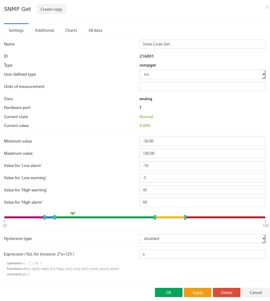
- Create an SNMP-GET element (analog) to read the device's status code. Set thresholds so that all expected codes are in the normal range.
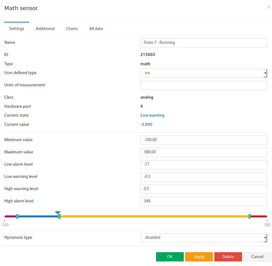
- Create a Math Sensor that detects a specific status code. Configure thresholds so that only the value
0is in the normal state (example: low warning level = −0.5; high warning level = 0.5). - Set the variable in the Math Sensor to the SNMP-GET element. In the formula field, subtract the target code: e.g.
A-7for status code 7. - Create additional Math Sensors for further status codes and combine them all in one group.
- Configure an email notification with macros that insert the current value and the element name into the message.
 🔍 Enlarge
The SNMP-GET Analog element reads the numeric status code. Thresholds are set so that all possible codes are in the normal range – to prevent false alarms.
 🔍 Enlarge
Formula:
A-7 (subtracts the target code). Only when the result value is 0 is the sensor in the normal state. Thresholds: Low warning level = −0.5, High warning level = 0.5.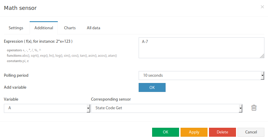 🔍 Enlarge
Variable
A is assigned to the SNMP-GET element (status code). The formula A-7 results in 0 when the current status code is 7 – the Math Sensor is then in the normal state.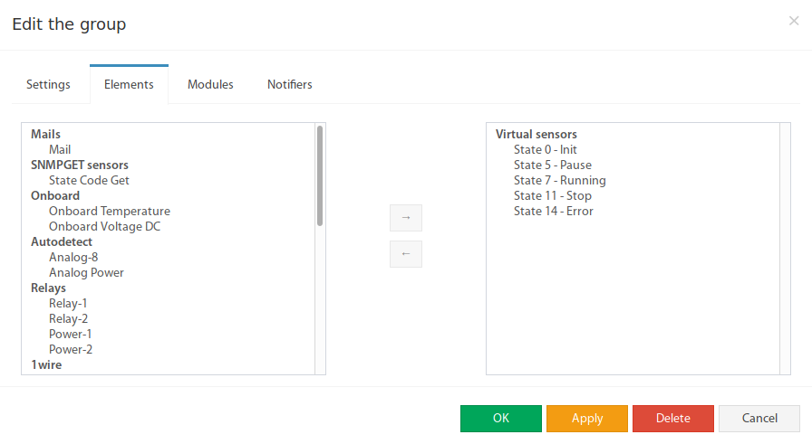 🔍 Enlarge
A separate Math Sensor is created for each status code to be monitored. All are combined in one group. When an element reaches the normal state, the notification is triggered.
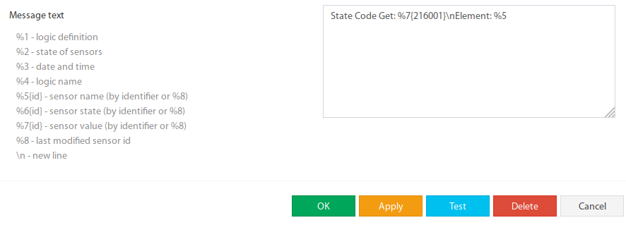 🔍 Enlarge
The email notification uses macros to automatically insert the current status code value and the element name into the message. This way every message contains the exact state.
Example Notification Text
Configure Cameras & Camera Panel
▼Didactum monitoring devices can integrate USB and IP cameras. The MJPEG stream from USB cameras can be recorded and sent as a video notification by email. IP cameras are only available for live view. The camera panel can be found under Main Menu → Cameras.
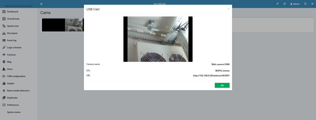 🔍 Enlarge
The camera panel shows all connected cameras. USB cameras appear automatically after connection. IP cameras can be added manually via the panel. Depending on the model, up to 2 USB cameras are supported.
Camera Types Comparison
| Feature | USB Camera | IP Camera |
|---|---|---|
| Connection | Direct USB connection | Network (LAN/WLAN) |
| Integration | Automatically detected | Manual addition |
| Recording | MJPEG stream recordable | Live view only |
| Video notification | ✅ Via email as AVI file | ❌ Not possible |
| Quantity (per model) | Max. 2 USB cameras | Depends on model |
Video Notifications via USB Webcam
▼A video notification is a short AVI video in MJPEG format that is automatically sent by email when a specific event occurs in the system – for example, in the case of a motion alarm on your Didactum device.
Setup Step by Step
- Create a new email notification or open an existing one.
- Create a logic circuit that triggers the video notification: Select the monitoring element and its state as the IF condition (e.g. motion sensor in Alarm state).
- As the THEN action, select the email notification and activate the corresponding state in the "Send Video" field.
 🔍 Enlarge
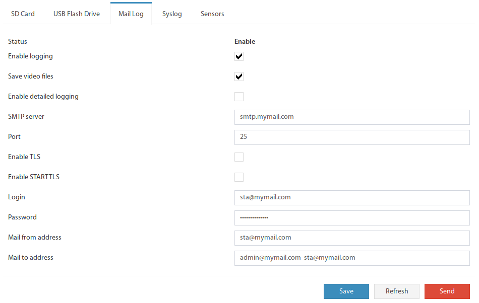
Enter all required data in the email notification form (recipient, subject, text). The "Send Video" option is activated later in the logic circuit.
 🔍 Enlarge
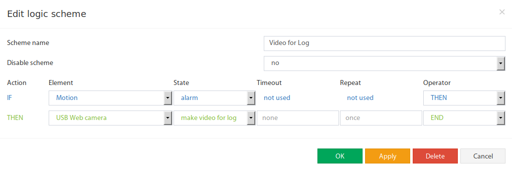
IF the motion sensor switches to Alarm state, THEN trigger email notification AND set field "Send Video" = active. This way a short video is automatically recorded and sent by email with every motion alarm.
Technical Details of the Video Format
| Property | Value |
|---|---|
| File Format | AVI (Audio Video Interleave) |
| Video Codec | MJPEG (Motion JPEG) |
| Length | A few seconds (depending on configuration) |
| Sending Method | Email attachment |
| Camera Type | USB webcam only (IP cameras not supported) |