


Didactum Monitoring Systems
Setting up Modem, SMS Commands & GPS
Complete guide for setting up the GSM/4G/LTE modem of your Didactum monitoring unit: SMS sending & receiving, SMS remote control, LTE internet connection, GPS positioning and RADIUS user management.
Setting up the Modem – Overview
Basics of GSM/4G modems on Didactum devicesDidactum monitoring systems (models 50T, 100T, 500T and 550T) can be equipped with a GSM or 4G/LTE modem. This enables sending SMS notifications, remote control of the device via SMS commands and – with compatible LTE modems – using an internet connection as a failover solution as well as GPS positioning.
The modems operate in Primary mode. If Primary mode is not available (e.g. no 4G reception), the modem automatically switches to Secondary mode (2G).
| Modem | 4G Support | 2G Support | Used in |
|---|---|---|---|
| 4G/LTE Modem Expansion Module | Primary | Secondary | Didactum 100T, 500T, 550T |
Using SMS Commands (Remote Control via SMS)
Example: Send alarm message & deactivate via SMSTask: Send alarm messages until the alarm is deactivated via SMS command or the conditions change.
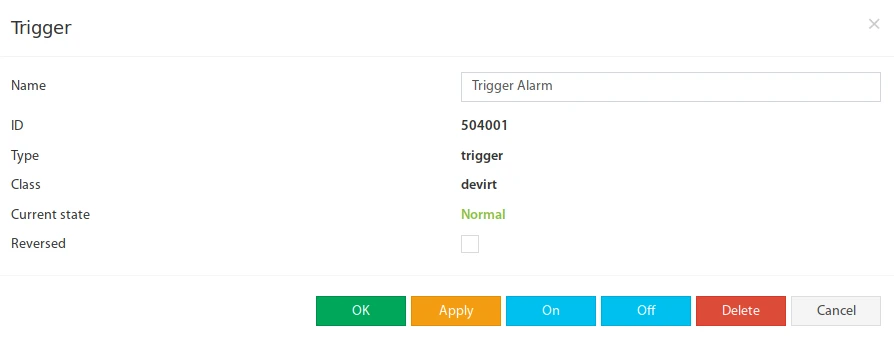
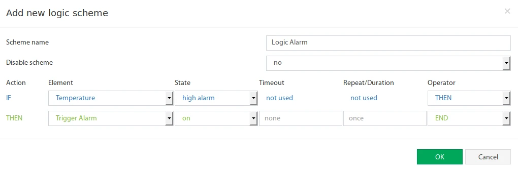
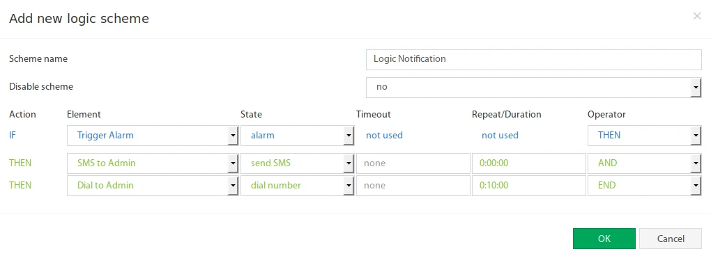
To implement this, a Trigger element is used as an intermediate step. The trigger is activated ("on") when an alarm occurs and deactivated ("off") when the condition returns to normal. As long as the trigger is active, notification and call actions are executed. The trigger can be deactivated via an SMS command when the notification is no longer needed.
Step 1 – Create Trigger Element “Trigger Alarm”
 🔍 Enlarge
Step 2 – Logic scheme for controlling the trigger
 🔍 Enlarge
Step 3 – Logic scheme for notifications
 🔍 Enlarge
Step 4 – Deactivate alarm prematurely via SMS
To deactivate the alarm prematurely once the notification has reached the recipient and no further messages are needed, the “Trigger Alarm” must be switched off. Enter the permitted phone numbers in the “List of allowed phone numbers” field on the “SMS messages” page. Then send the following SMS:
| SMS Command | Note |
|---|---|
Set 'Trigger Alarm' off | The element name must be in quotation marks and is case-sensitive. |
The element (Trigger Alarm) was switched offSMS Gate: Sending SMS via another Didactum Device
SMS sending via a device with built-in GSM modemDevices without their own GSM/4G modem (e.g. a Didactum 50T without modem option) can send SMS notifications via another Didactum device equipped with a GSM modem (so-called SMS Gate).
Forwarding Incoming SMS & Receiving SMS Commands
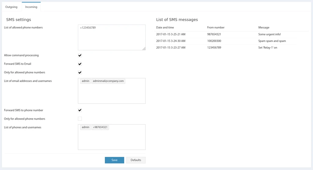
Query status, switch relays and control logic via SMSWith this function, incoming SMS can be received and their content forwarded to other phone numbers or email addresses. The settings are located on the “SMS messages” page, tab “Incoming”.
 🔍 Enlarge
Available Settings
| Setting | Description |
|---|---|
| List of allowed phone numbers | List of phone numbers from which incoming SMS will be accepted for processing. |
| Allow command processing | Enables incoming SMS commands. Only commands from allowed phone numbers are processed. |
| Forward SMS to Email | Forwards incoming SMS to configured email addresses. The SMTP settings must be configured under Preferences → SMTP. |
| ↳ Only for allowed phone numbers | Forward to email only for allowed phone numbers. |
| ↳ List of email addresses and usernames | List of email addresses or usernames to which the SMS text will be forwarded. |
| Forward SMS to phone number | Forwards incoming SMS to configured phone numbers. |
| ↳ Only for allowed phone numbers | Forward to phone only for allowed phone numbers. |
| ↳ List of phones and usernames | List of phone numbers or usernames to which the SMS text will be forwarded. |
+. Up to 20 phone numbers are possible. This applies to allowed numbers, forwarding numbers and numbers for single SMS sending.SMS Commands for Remote Control
SMS commands allow remote control of the monitoring system: reading system status, sensor values and group values as well as switching relays (outlets). Authorized phone numbers are entered under Main menu → SMS messages → List of allowed phone numbers.
1. Read Status: get
Syntax: get [ID] or get [Name] – ID is the element ID number, Name is the name of the element. “get” is not case-sensitive (also Get, GET possible). The name must be in quotation marks, is case-sensitive and must be unique.
The reply SMS contains the status of the requested sensor or relay.
| Command | Example Reply |
|---|---|
get systemReturns device information: type, firmware, status, IP address etc. |
System: 100T |
get [Group name or ID]Returns group description and short overview of all modules/sensors. |
Group: test group [3001] |
get [Sensor name or ID]Returns status & measured value of the sensor. |
Element: Temperature-1 [201003] |
2. Switch Relays / Outlets: set
Syntax: set [ID] [state] or set [Name] [state] – state can be on (switch on) or off (switch off). The name is case-sensitive.
| Example | Effect |
|---|---|
set '302001' on | Switches relay No. 302001 on. |
set 'Outlet-1' on | Switches relay “Outlet-1” on. |
set '302002' off | Switches relay No. 302002 off. |
set 'Outlet-2' off | Switches relay “Outlet-2” off. |
Reply: The element (Elementname) was switched on or ... was switched off
3. Relay Pulse: set ... pulse
Syntax: set [ID] pulse {Duration} or set [Name] pulse {Duration} – Duration is the delay in seconds (range 1–120). If no duration is specified, the previously set value is used. The command toggles the relay twice (pulse) with the specified delay.
| Example | Effect |
|---|---|
set '302003' pulse 15 | Pulse on relay No. 302003 with 15 seconds delay. |
set 'Relay-1' pulse 110 | Pulse on relay “Relay-1” with 110 seconds delay. |
set 'Outlet-2' pulse | Pulse on “Outlet-2” with the previously set delay. |
Reply: The element (Elementname) was switched
4. Control Logic Schemes: logic
Syntax: logic [ID] [state] {Duration} or logic * [state] – ID is the logic number (* = all logics), state is on or off, Duration is the deactivation time in seconds (only for single logic). All fields are not case-sensitive.
| Example | Effect |
|---|---|
logic 1 off 10 | Deactivates logic No. 1 for 10 seconds. |
logic 1 on | Activates logic No. 1. |
logic * off | Deactivates all logics for 24 hours. |
logic * on | Activates all logics. |
Reply: OK
User Management & RADIUS Authentication (API)
Permissions, user accounts and central authentication via RADIUSThis section is aimed at technically experienced users and integrators who want to manage user accounts and permissions directly via the API or set up central authentication via a RADIUS server.
Permission Concept
Each user profile can access system resources with read-only or read-write permissions. Each resource has an access identifier; access control is done via comma-separated lists of identifiers.
| List Type | Meaning |
|---|---|
SRead / SWrite | Server permissions (read / write access to server resources such as GSM, relays, sensors, users etc.) |
CRead / CWrite | Client permissions (web interface functions such as Dashboard, Timeline) |
GRead / GWrite | Group permissions (access to object groups based on group IDs) |
Important server resource IDs (selection): accesskeys, cameras, canbus, devvirt, elements, groups, gsm, log, logics, modules, notify, relays, sdcard, system, users, view as well as all (full access to all resources).
For group permissions (GRead/GWrite) the following also applies: all = full access to all groups, none = access completely denied. By default, elements are not assigned to any group – access is then only possible with all.
guest with password guest (SHA-1 hash). For security reasons, this default password should be changed immediately.Authentication & Session
During login (querytype=auth, fields name and password hash h) the client receives a Session Key (k), which is used to authenticate all further API calls. Alternatively, login via PIN code is possible (querytype=authpin, fields name and n, 4–8 digits).
The session is terminated with querytype=authclose and passing the session key. After a system restart, all sessions are lost – a new login is required.
Reading, Creating and Deleting User Accounts
| Action | querytype | Important Fields |
|---|---|---|
| Read user(data) | getuser | k (Session Key), optional id – without ID all users are listed |
| Create / modify user | adduser | k, optional id (for modification), name, h (password hash), sread, swrite, cread, cwrite, gread, gwrite, mail, phone, pin |
| Delete user | deluser | k, id of the user to be deleted. Your own account cannot be deleted. |
Valid=0). Recovery via the API is not provided.Central Authentication via RADIUS
Alternatively to the local user database, login can be done via an external RADIUS server. Login is two-stage: First the user is searched in the local database; if not found, a request is sent to the RADIUS server.
| Action | querytype | Fields |
|---|---|---|
| Enable / configure RADIUS | setradius | k, enable (1/0), addr (server address), port (usually 1812), secret (password) |
| Read RADIUS configuration | getradius | k |
Vendor-Specific Attributes (Vendor Code 39052)
On the RADIUS server, the manufacturer-specific dictionary dictionary.local must be placed in the directory /etc/raddb/ and included in the main dictionary file.
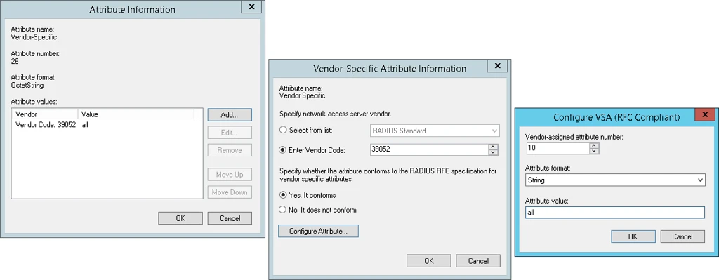 🔍 Enlarge
| Attribute Name | Number | Format | Value |
|---|---|---|---|
| SRead | 10 | String | all or permission list |
| SWrite | 11 | String | all or permission list |
| CRead | 12 | String | all |
| CWrite | 13 | String | all |
| GRead | 14 | String | all or group IDs |
| GWrite | 15 | String | all or group IDs |
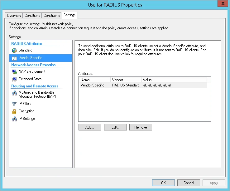 🔍 Enlarge
Example Configuration Files
username01 receives full access when logging in via IP 192.168.1.88. When logging in via all other device IPs, restricted write permissions apply.LTE Modem Mode & Internet Connection
Check signal strength, send test SMS, use LTE as internet failoverCheck if the modem is ready for operation
- Insert the SIM card into the modem. Ensure there is sufficient credit or a valid LTE contract.
- Make sure the external antennas are attached to the modem – both “MAIN” and “AUXILIARY”.
- Switch on the system. The modem is automatically detected during boot.
- If the SIM card is inserted while the system is already on, network registration can take up to 15 minutes.
- Upon successful modem detection, the menu item “SMS messages” will appear.
- Check signal strength (example: 48 %).
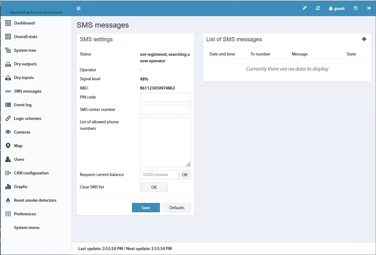 🔍 Enlarge
Send test SMS
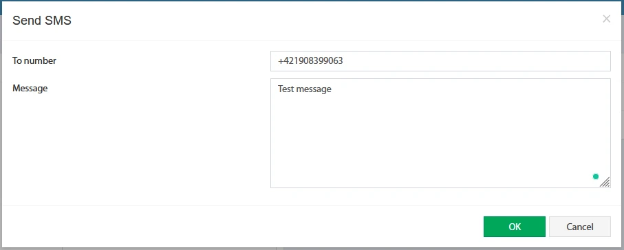
- Click on the “+” to the right of “List of SMS messages” – a window for sending a test SMS will open.
- Enter the mobile number and message text and click “OK”.
- The SMS should arrive on the specified mobile phone.
- A confirmation of successful sending will appear in the web interface.
 🔍 Enlarge
 🔍 Enlarge
Internet connection via LTE
Starting with firmware version 2.7.4, the LTE modem can additionally be used for connection to internet services (VPN, SMTP, FTP etc.) as well as for remote access to the device. The settings can be found under Preferences → LTE.
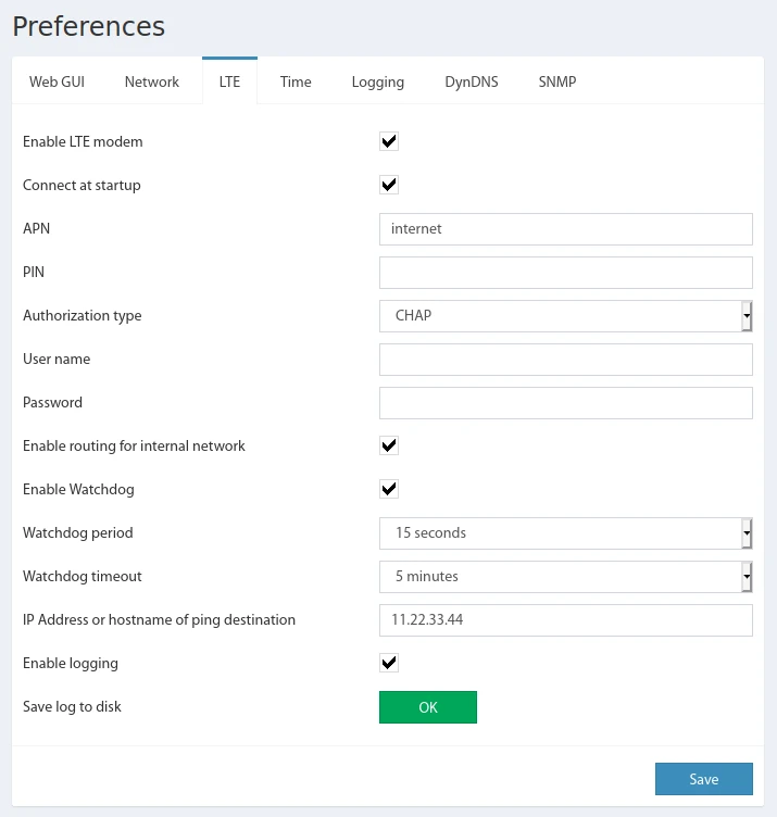 🔍 Enlarge
| Setting | Description |
|---|---|
| Enable LTE modem | Enables/disables the LTE modem (if supported). |
| Connect at startup | Connection mode: permanently connected from system start, or connection only on demand (failover). |
| APN | Access Point Name of the mobile network provider. |
| PIN | PIN code of the SIM card, if required. |
| Authorization type | Authentication method: PAP, CHAP or none. |
| User name / Password | Access credentials of the mobile provider, if required. |
| Enable routing for the internal network | Allows internal network devices to use the LTE connection as a gateway for internet access. |
| Enable Watchdog | Enables watchdog ping to monitor the connection. |
| Watchdog period | Interval of watchdog pings in seconds. |
| Watchdog timeout | Time without response after which the connection is considered interrupted (seconds). |
| IP Address or hostname of ping destination | Destination address for checking the LTE connection. |
| Enable logging / Save the log to disk | Enable connection log / save to disk (only for troubleshooting, do not leave permanently active). |
For a permanent internet connection, we also recommend using an OpenVPN client: The VPN connection remains active both via Ethernet and via LTE (in case of Ethernet failure) and thus ensures permanent access to the protected network as well as a fixed IP address of the device.
Accessing the device via LTE from the internet
If the SIM card supports a private APN with a static IP address, the device can be reached directly via this IP (inquiry with the mobile provider required). You can find the assigned LTE IP address in the “Network” tab (field “LTE IP address”).
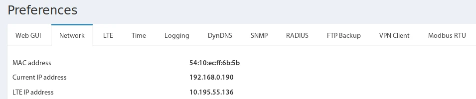 🔍 Enlarge
| Field | Description |
|---|---|
| MAC address | Unique 12-digit alphanumeric hardware address for identifying the device in the Ethernet network. |
| Current IP address | Current IP address in the Ethernet network – statically configured or assigned via DHCP. |
| LTE IP address | IP address assigned by the mobile network provider. This can be Static (static) or Dynamic (dynamic):
• A static IP address is always “Whitelisted” – ports 80, 443 etc. are open, the device is reachable via this IP. • A dynamic IP address can be “Whitelisted” or “Greylisted”. “Greylisted” means that ports are closed by the provider’s NAT and no access is possible via this IP. • If the web interface is reachable via this IP address, it is “Whitelisted”. Whether an IP is static/dynamic or white-/greylisted depends on the mobile contract and cannot be automatically checked by the device. |
Setting up 4G Modem
Configure SMS sending & receiving – Basic setupThe modem is used in the system for sending SMS notifications and receiving SMS commands.
Basic procedure
- Insert the SIM card into a mobile phone and check functionality and PIN code.
- Insert the SIM card into the modem.
- Switch on the monitoring system.
- Configure the modem (see below).
- Set up SMS notifications and configure appropriate logic schemes or group notifications.
Modem configuration
Modem configuration is done in the Main Menu → SMS messages tab.
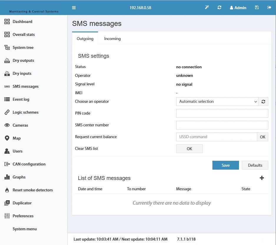 🔍 Enlarge
| Field | Description |
|---|---|
| Status | State of the mobile network. |
| Operator | Name of the currently used mobile network operator. |
| Signal level | Signal strength in percent. |
| IMEI | Unique international device identifier (International Mobile Equipment Identity) of the LTE modem. It is only displayed in the web interface after inserting the SIM card (update may take up to 5 minutes). Your mobile provider needs this number to register the device in the network. |
| PIN code | PIN code of the SIM card. |
| Choose an operator | Current list of available GSM network operators including refresh button. |
| SMS center number | Number of the SMS center of the provider. Leave blank for automatic detection – we recommend manual entry, as some SIM cards have problems with auto-detection. |
| Request current balance | USSD code to query the balance. After clicking “OK”, the response is displayed in the log. |
| Clear SMS list | Clears the list of sent SMS messages. |
- Insert SIM card correctly and switch on the modem.
- Read the IMEI number in the web interface under the modem settings.
- Send the IMEI number to your mobile provider and request registration of the device in the network.
*, e.g. *111# or *222*. Do not enter a phone number here. Some providers no longer support USSD.If a modem error occurs, no SIM card is inserted or the PIN code is wrong, a corresponding message is written to the log queue (“GSM modem: Error, check your SIM card and PIN code” or “GSM modem: modem error, restart smsd”). The message is displayed a maximum of 5 times to avoid filling the log.
The “List of SMS messages” shows up to 100 of the most recently sent SMS (up to 1000 on VT9xx systems). This list is not saved when the device is restarted.
GSM Network Operator List
The operator list is automatically updated at regular intervals after switching on and can be manually refreshed using the button. The retrieval can take several minutes; on success, a corresponding log message appears. If no connection can be established to the selected operator, the modem switches to automatic selection mode. The currently used operator is displayed in the “Operator” field.
GSM Modem Elements in the System Tree
In the “System Tree” menu there are elements that display the status of the modem. These do not affect the state of the “System” element and can be used in logic schemes.
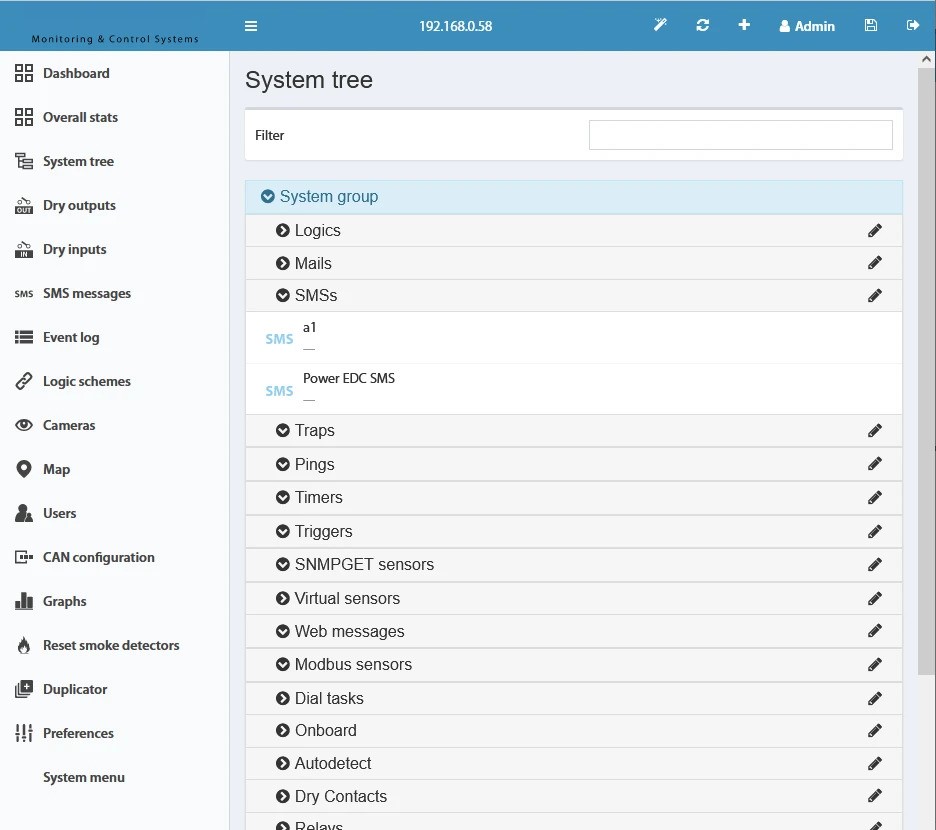 🔍 Enlarge
| Element | Description |
|---|---|
| GSM Signal Level | Analog value – shows the signal strength in percent (0–100 %). |
| GSM State | Not connected – connection not yet established |
Alarm – an error has occurred | |
Normal – connection successfully established | |
| LTE State | Not connected – connection not yet established or disabled |
Alarm – an error has occurred | |
Normal – connection successfully established |
Setting up SMS notifications
Open the “SMS” window in the “System Tree” menu to add a notification recipient:
| Field | Description |
|---|---|
| Name | Any name for the notification (e.g. name or position of the recipient). |
| Phone number | Phone number to which the notification is sent. |
| Message text | Any text. Current sensor values can be inserted into the text using macros %1–%8. |
Click “Save” to apply the settings. Use “Test” to send a test SMS (note: test messages may contain incorrect sensor data for the macros %1/%2 – this is normal for testing purposes).
After configuring the recipient, the event that triggers the SMS must be defined under Preferences → Logic schemes → Add. A maximum of 15 SMS recipients can be stored per logic scheme for one or more events. If more than 15 recipients are needed for the same event, an additional logic scheme with the same input condition must be created.
SMS messages are placed in a queue (max. 100 messages) so that it does not have to wait for the completion of the previous sending. On overflow, already sent messages are automatically deleted. Sending information is logged in the system log.
- Negative balance on the SIM card
- Too low signal strength
- Wrong format or non-existent recipient phone number
SMS sending via third-party programs (e.g. cURL)
SMS can also be sent via external programs such as cURL. The following Bash script shows the process for firmware version 2.4.x and higher: Authentication at the web interface, determination of the session key and sending the SMS via the HTTP(S) endpoint engine.htm.
GPS Location
GPS positioning via the 4G/LTE modemThe 4G/LTE Modem supports GPS location information if a suitable GPS antenna is connected. A prerequisite is an inserted SIM card and an existing connection to the GSM network. Older LTE modems also support GPS positioning.
The GPS settings and information can be found under Preferences → GPS.
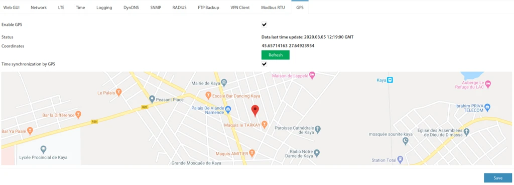 🔍 Enlarge
| Setting | Description |
|---|---|
| Enable GPS | Enables or disables the GPS function (if supported by the modem). |
| Status | Status text for the connection state. |
| Coordinates | GPS position as latitude and longitude (in degrees). |
| Time synchronization by GPS | Synchronizes the system time based on the GPS signal. |