


Didactum Monitoring Systems
Advanced Configuration
Complete guide to advanced configuration: AC/DC measuring devices, groups, CAN bus, logic schemes, floor plan, triggers and more – for all Didactum devices.
Configure AC/DC Measuring Devices
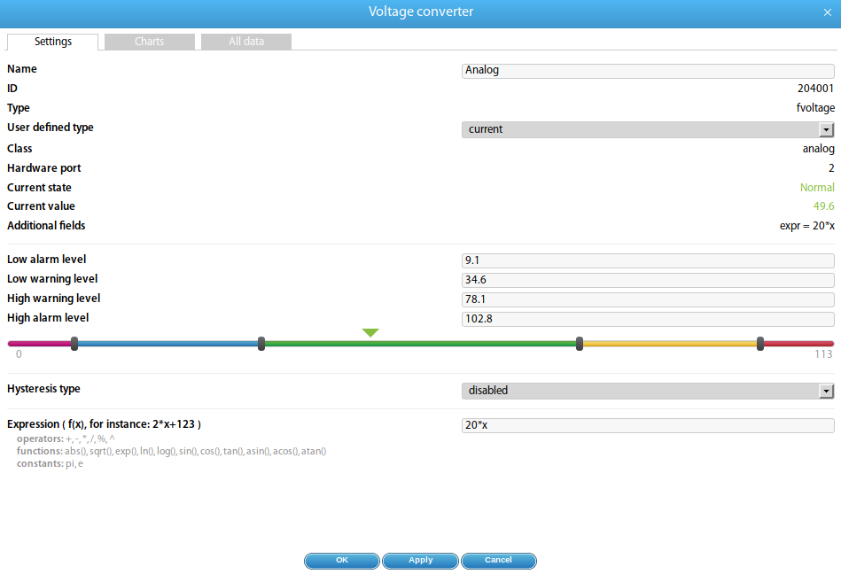
▼To configure current and voltage measuring devices such as compatible transducers (e.g. current transformers with K = 20 or voltage sensor up to 75 V), navigate in the web interface to Main Menu → System Tree and click on the corresponding sensor element. A modal window with the sensor properties will open.
 🔍 Enlarge
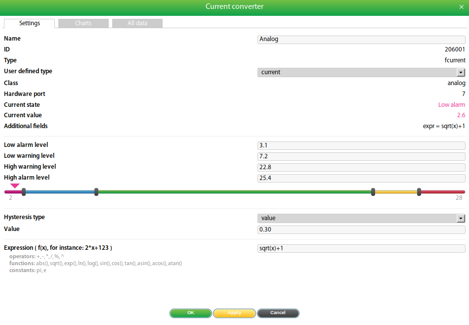
Properties of all measuring devices
| # | Field | Description |
|---|---|---|
| 1 | Name | Automatically assigned by the system – can be changed freely. |
| 2 | Group | Groups manually created by the administrator in the "Group Tree" menu. |
| 3 | ID | System ID of the element (not changeable). |
| 4 | Type | 4-20mA sensor or 0-5V voltage sensor. |
| 5 | Class | Analog |
 🔍 Enlarge
Conversion Formula (Expression)
If a measuring device (e.g. a 4-20mA current transducer) is used with external equipment such as a wind gauge or ultrasonic level sensor, a custom formula for value conversion can be entered.
By default: x (measured raw value). The following operators and functions are allowed:
- Operators:
+-*/%(remainder)^(power) - Functions:
abs,sqrt,exp,ln,log,sin,cos,tan,asin,acos,atan - Constants:
pi(3.1415926…),e(2.7182818…) - Decimal separator: Period, e.g.
2.123*x+123.111
Create Element Groups
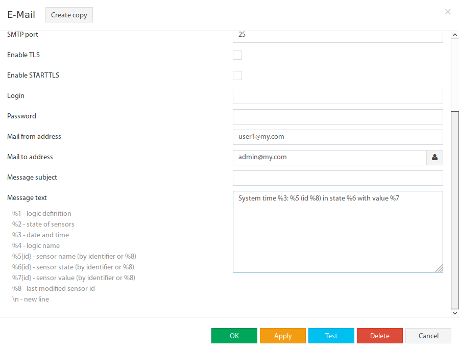
▼Groups are used for the structural organization of elements in the system. They allow multiple sensors or devices to be combined and common notifications to be defined.
Create New Group
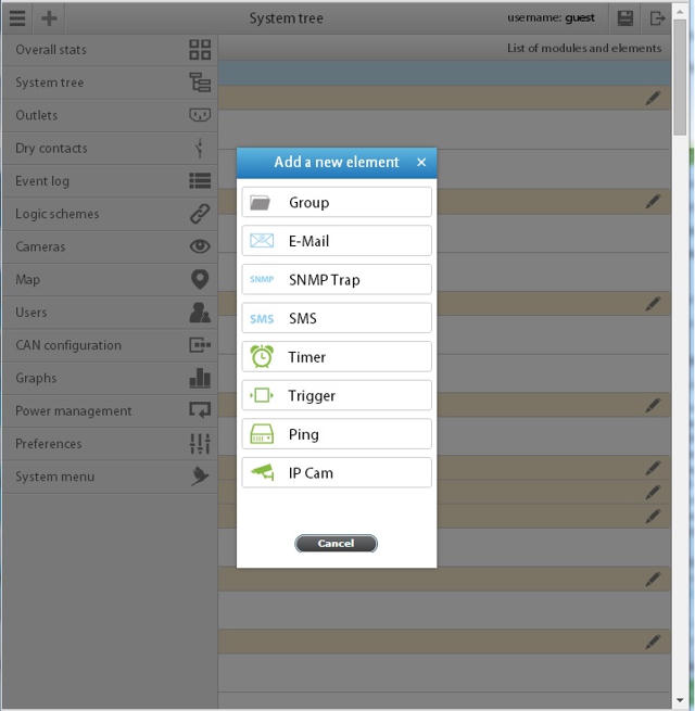
- Navigate to Main Menu → System Tree and click the "+" button.
- Select "Group" from the dropdown. A modal window will open.
- Enter a Name and optionally a Description for the group.
- Add the desired elements and modules to the group.
- Confirm with "OK".
 🔍 Enlarge
 🔍 Enlarge
 🔍 Enlarge
Configure CAN Bus
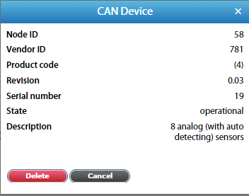
▼The CAN configuration panel is used to set up the CAN bus for digital CAN sensors and expansion devices. Devices can be connected in a daisy-chain to the CAN port. All configured CAN sensors will then appear in the System Tree.
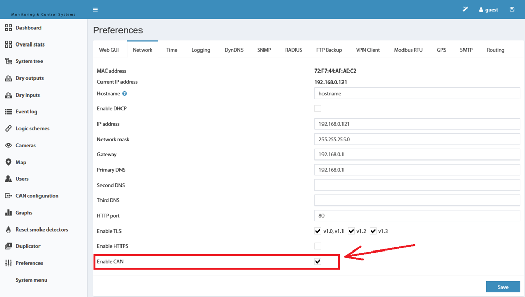
Enable CAN
- Navigate in the web interface to Settings Menu → Network Tab.
- Enable the option "Enable CAN".
- Click "Save", then click the "Save Settings to Flash" icon (top right).
 🔍 Enlarge
Configure CAN
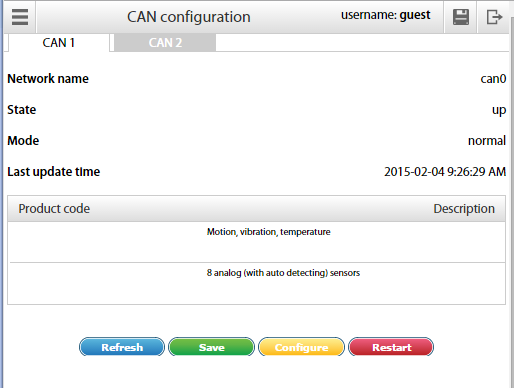
Before a CAN sensor module can be operated, the CAN bus must be configured. Navigate to Main Menu → CAN Configuration.
 🔍 Enlarge
Available Actions
| Action | Description |
|---|---|
| Refresh | Updates the current status information of the node. |
| Configure | Starts the configuration process for the connected CAN sensor modules. The old configuration will be lost. |
| Save | Saves the list of CAN sensor modules to flash memory. |
| Restart | Restarts the CAN bus node. |
 🔍 Enlarge
{ModuleName}{SerialNumber}-{SensorType} and can be edited later.Logic Schemes
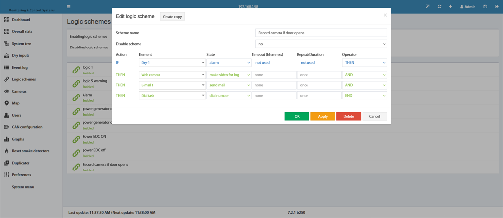
▼Logic schemes are used to define automatic actions in response to events in the system. They consist of a set of IF conditions and THEN actions. Conditions can be linked with AND and OR.
A logic scheme is only active when the combination of conditions is met. If it is inactive, no reverse actions are executed either – a separate logic scheme is required for this.
 🔍 Enlarge
Create New Logic Scheme
- Navigate to Main Menu → Logic Schemes and click on "+". A modal window will open.
- Enter a Name for the logic scheme.
- Create the IF conditions: Select the desired element in the "Element" field and the triggering state in the "State" field. Use "AND" / "OR" in the "Operator" field to link additional conditions.
- Define the THEN actions. A delay in seconds can be entered in the "Timeout" field before the element assumes the new state.
- In the "Repeat" field, you can set a repeat interval for the entire duration of the activity (e.g. for periodic email sending).
- Save the logic scheme and save the settings to flash memory.
🔍 Enlarge
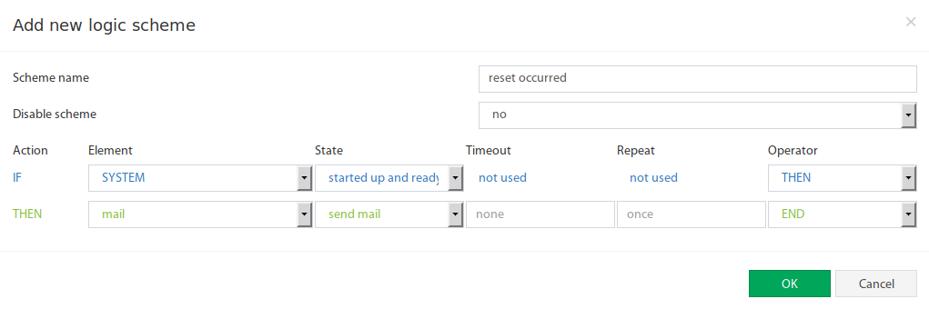
One-time Actions on System Startup
Logic schemes can be configured to run once when the system boots. A forced system restart via logic scheme is also possible – however, use this with caution if log files are saved via email or FTP. The system will not restart if less than 15 minutes have passed since the last start.
 🔍 Enlarge
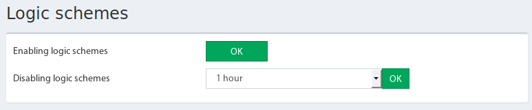
Deactivate/Activate All Logic Schemes Simultaneously
 🔍 Enlarge
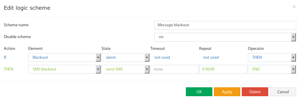
Example 1: AC Sensor Alarm (Power Failure)
▼This example shows how an AC voltage sensor is used to detect power failures. Three states are monitored: power present, short outage, and long power outage (blackout).
Objective
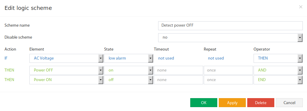
- Trigger an alarm when voltage drops (power "OFF")
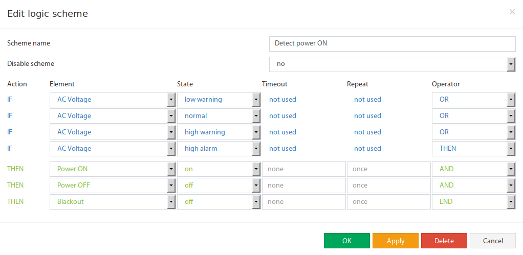
- Send a clear message when voltage returns (power "ON")
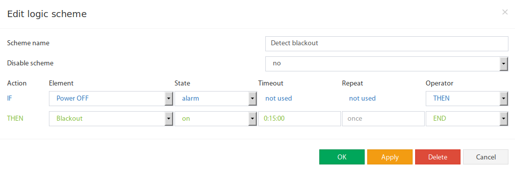
- Mark a longer power outage (e.g. > 15 minutes) as an emergency (blackout)
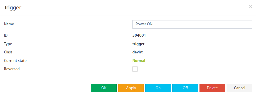
Step 1: Create Three Triggers
Create three triggers (→ see Section 9: Create Triggers):
- "Power ON" – corresponds to the state "Power present"
- "Power OFF" – corresponds to the state "short outage"
- "Blackout" – corresponds to a long power outage (emergency)
 🔍 Enlarge
Step 2: Set Voltage Sensor Thresholds
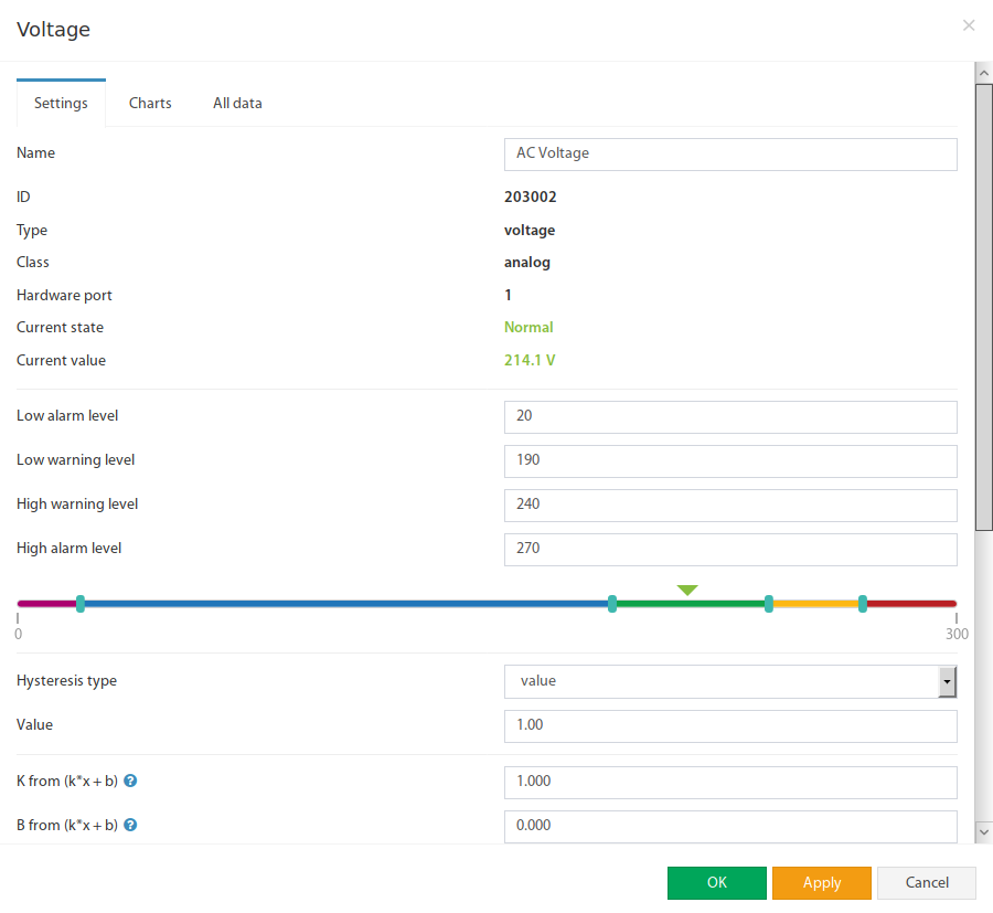
Set the "Low Alarm" threshold to a value greater than zero, because the sensor may still display a few volts during a power failure (residual voltage).
 🔍 Enlarge
Step 3: Create Logic Schemes
 🔍 Enlarge
 🔍 Enlarge
 🔍 Enlarge
 🔍 Enlarge
Example 2: Activate Fan & Siren on Temperature Alarm
▼This example shows how fans are automatically activated in a telecommunications cabinet and, in case of critical overheating, an additional siren and notifications are triggered.
Components Used
| # | Device/Element | Description |
|---|---|---|
| 1 | Temperature Sensor | Built into the server cabinet |
| 2 | Power-1 Fan | Controls the fans (relay output) |
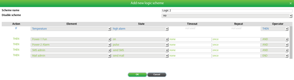
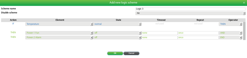
| 3 | Power-2 Alarm | Controls the siren (relay output) |
| 4 | Mail Admin | Email notification (created by the user) |
| 5 | SMS Admin | SMS notification (created by the user) |
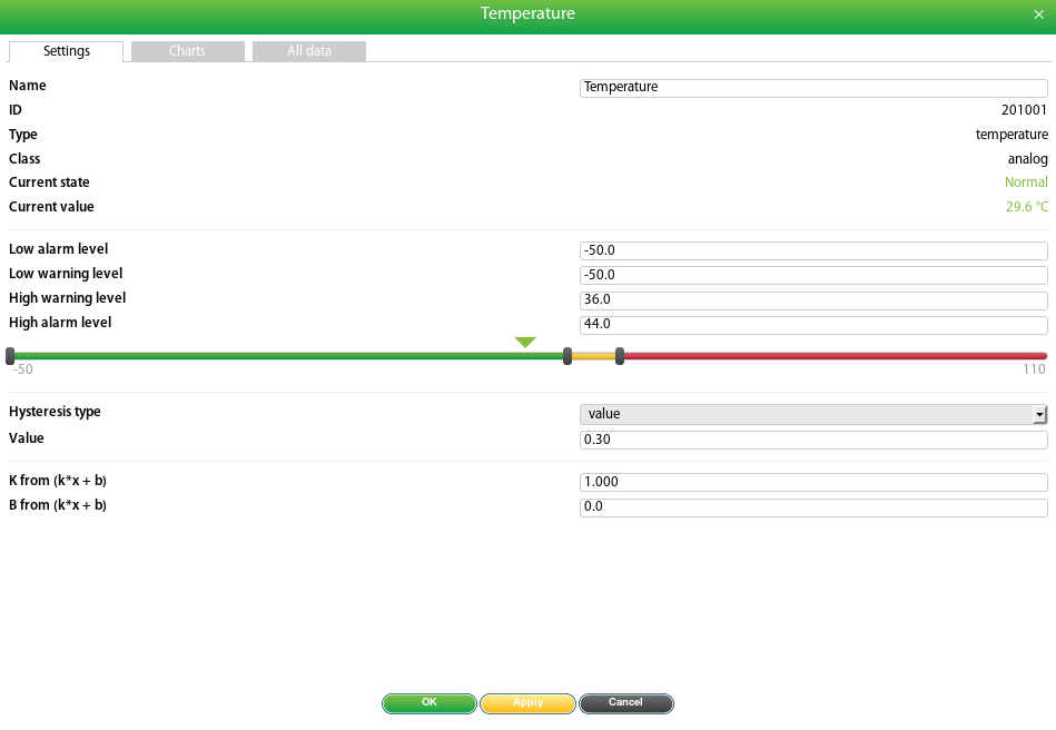
- Adjust temperature sensor thresholds: Set "High Warning" to 36°C and "High Alarm" to 44°C. Set unused lower thresholds to minimum.
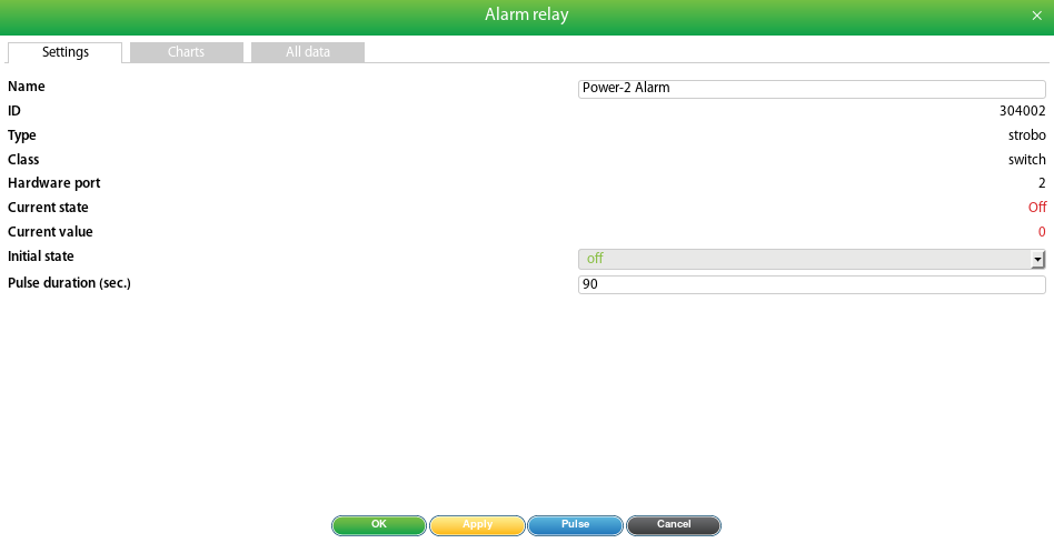
- Configure relay settings: Assign a name and define the "Pulse Duration" (determines how long the siren is active, e.g. 90 seconds).
- Create email and SMS notifications (→ Create notifications).
- In the Logic Schemes menu, create three logics (see below).
 🔍 Enlarge
 🔍 Enlarge
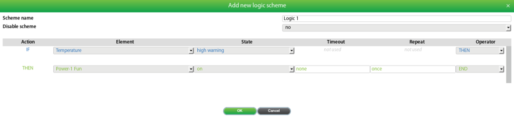
a) Logic Scheme 1: Activate Fan at 36°C
 🔍 Enlarge
b) Logic Scheme 2: Fan + Siren + Notification at 44°C
 🔍 Enlarge
c) Logic Scheme 3: Deactivate Fan at Normal Temperature
 🔍 Enlarge
Example 3: Switch on AC Device on Motion
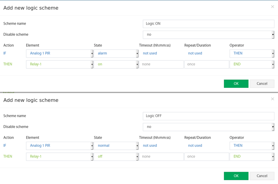
▼This example shows how a PIR motion sensor automatically switches an AC device (e.g. a lamp) on and off.
- Connect the PIR sensor to an analog port (compatible PIR sensors for Didactum devices).
- Connect the AC line (e.g. 110 VAC circuit for a lamp) to the relay switch of the monitoring system.
- Create two logic schemes – one to switch on and one to switch off the circuit.
 🔍 Enlarge
Create Floor Plan (Floor Map)
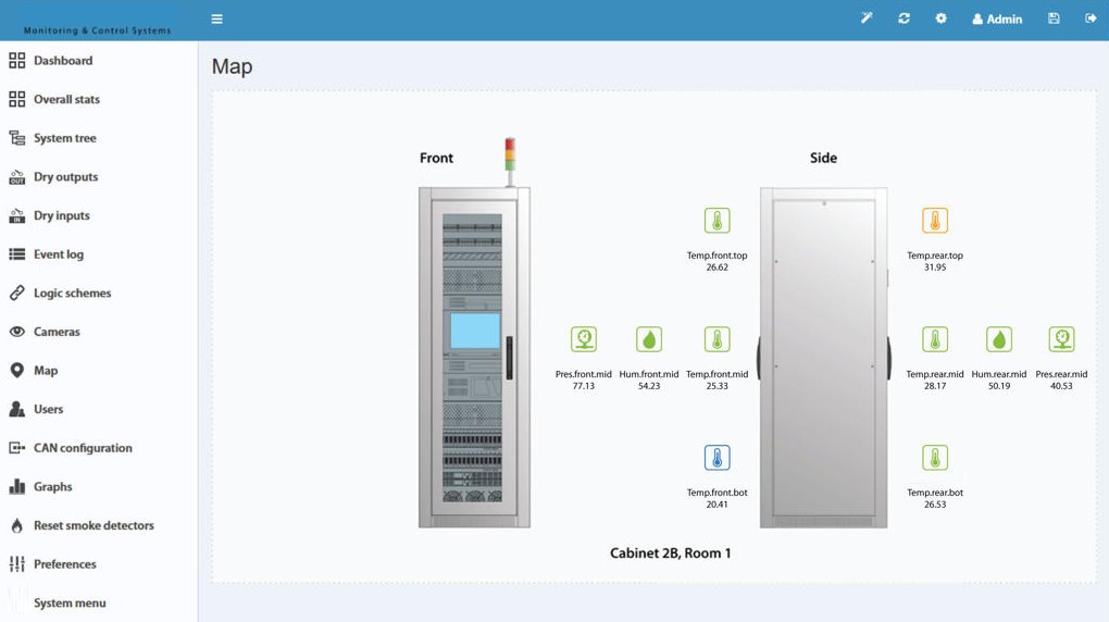
▼The map module allows uploading floor plans for multiple floors, rooms or racks. Sensors can be placed on the plan using drag-and-drop. In addition, vector graphic elements can be drawn (e.g. to visualize leakage sensor cables).
 🔍 Enlarge
Upload Floor Plan
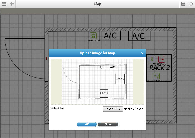
- Navigate to Main Menu → Map and click the settings icon "⚙".
- Select "New Map" → "Choose File" → upload image → "OK".
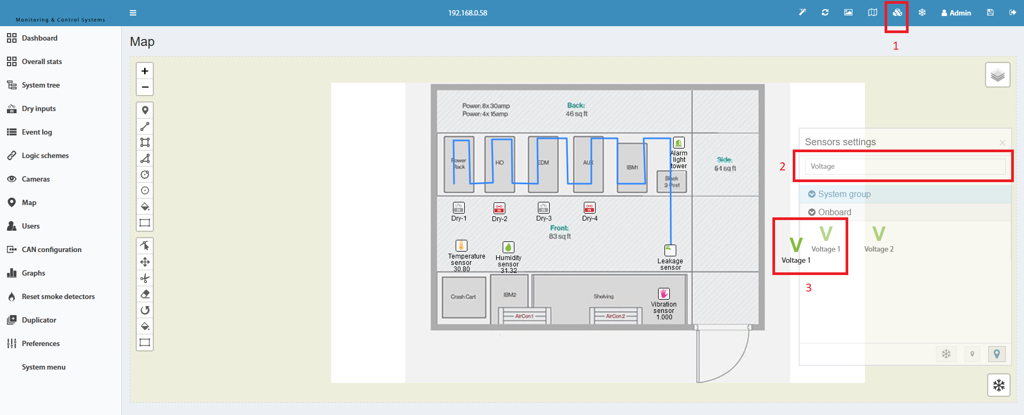
- To add/remove elements on the map: "⚙" → select elements → "OK" → drag and drop elements to the desired position.
 🔍 Enlarge
Place Sensors on the Plan
 🔍 Enlarge
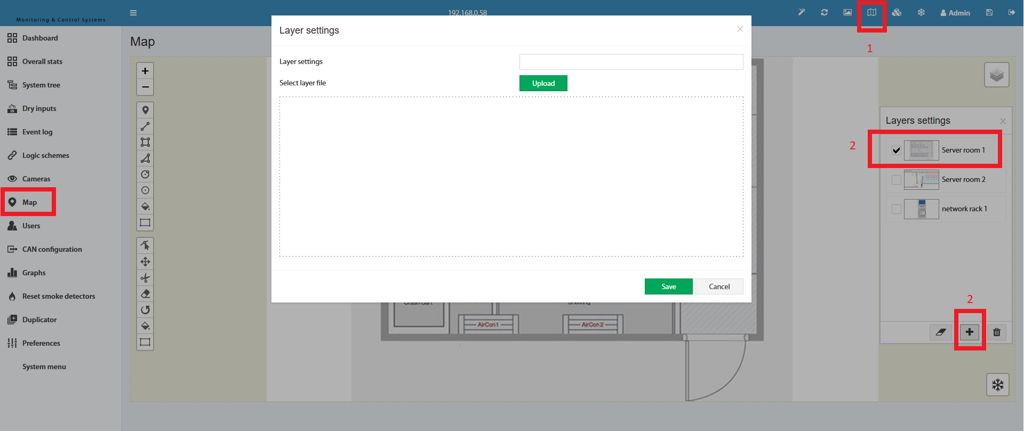
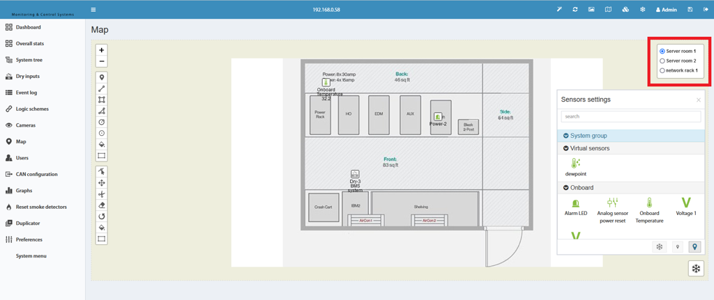
Create Multiple Floors/Rooms
- In the map area, click the "Maps" symbol in the top right to open the editing options.
- Create a new floor by clicking "+" or edit an existing floor by clicking on it.
- Upload a new image as background for the new floor.
 🔍 Enlarge
 🔍 Enlarge
Draw Vector Graphic Elements
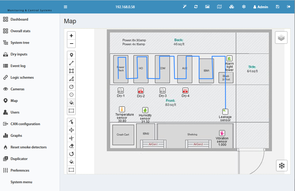
With the Polyline Tool (Draw Polyline) you can, for example, trace leakage sensor cables on the floor plan – exactly as they are installed in the room.
 🔍 Enlarge
Create Triggers
▼The trigger element is used to generate events in the system – triggered by logic schemes or manually. A trigger has two modes:
- Normal Mode: Changes from "Normal" to "Alarm" when activated, and back to "Normal" when deactivated.
- Inverted Mode: Reversed behavior.
A special feature of the trigger is that it can be used both in the IF condition list and in the THEN action list of logic schemes. This allows two independent logics to be linked together.
Create New Trigger
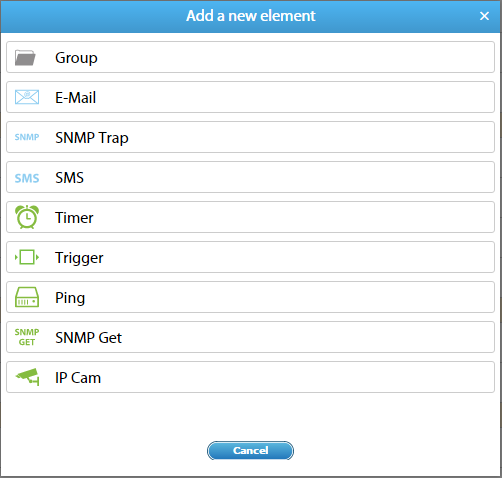
- Navigate to Main Menu → System Tree and click on "+".
- Select "Trigger".
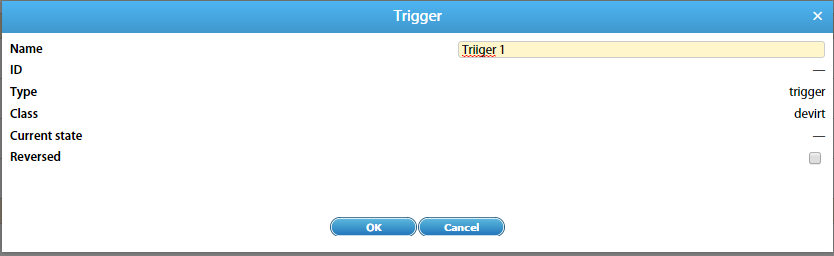
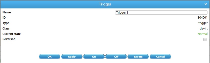
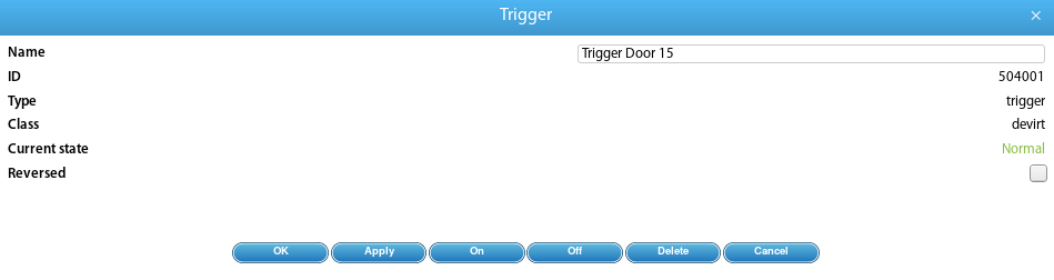
- Enter a Name for the trigger and, if required, select Inversion.
- Confirm with "OK".
 🔍 Enlarge
 🔍 Enlarge
 🔍 Enlarge
Using Triggers – Practical Examples
▼Triggers are extremely versatile and can be used to implement complex automation logics. The following four scenarios show typical use cases.
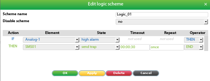
An analog sensor (e.g. voltage monitoring) shows frequent measurement spikes. A direct notification would generate too many messages.
Option 1: Delay (Timeout)
Create a logic scheme with a timeout field (e.g. 30 seconds). An SMS is only sent if the sensor remains in the High Alarm state for at least 30 seconds.
 🔍 Enlarge
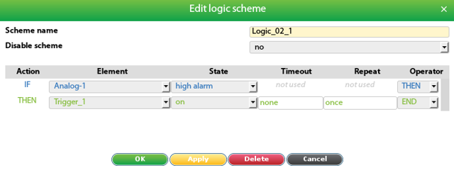
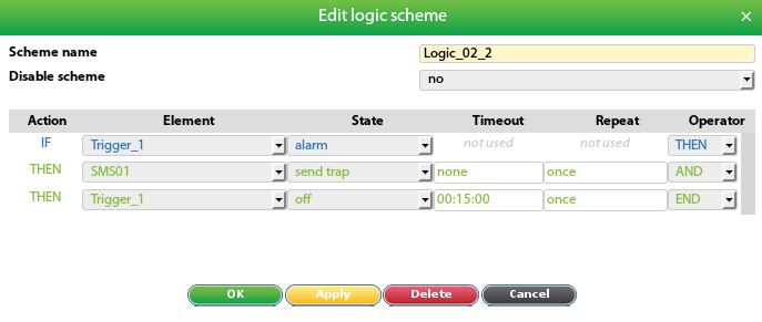
Option 2: Trigger as Intermediate Memory (max. one message every 15 min.)
 🔍 Enlarge
 🔍 Enlarge
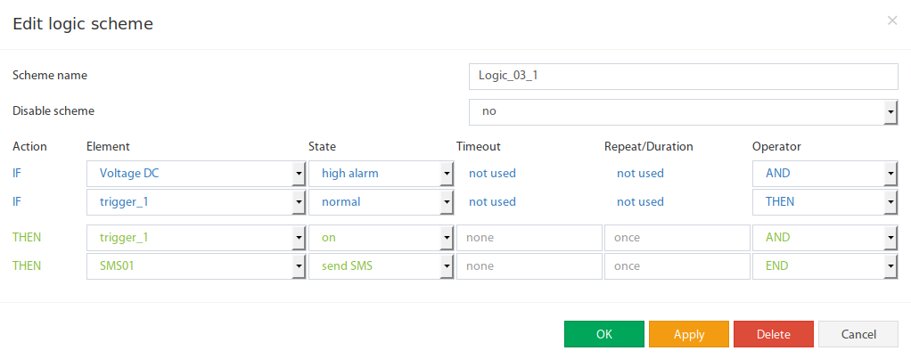
Option 3: React only to first High Alarm, ignore until Normal
 🔍 Enlarge
When the door of a server room is opened, the temperature can rise temporarily. No alarm should be triggered in this case.
- Create a trigger that "remembers" the door opening moment.
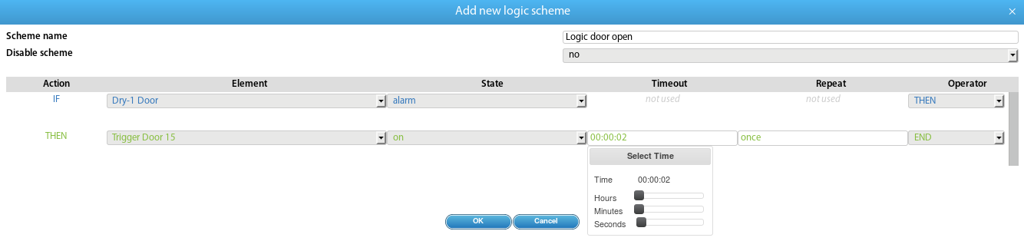
- Logic scheme: Activate trigger when the door is opened (with 2s delay to prevent accidental triggering).
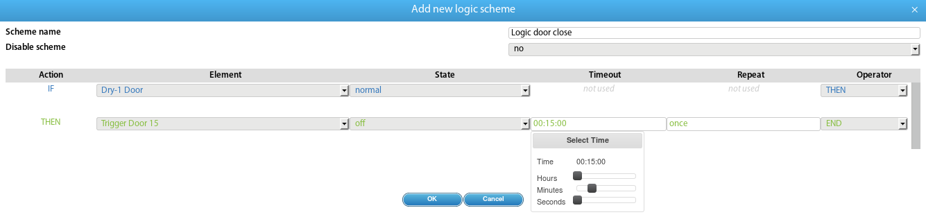
- Logic scheme: Deactivate trigger 15 minutes after the door is closed.
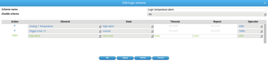
- Alarm logic scheme: Only send notification if trigger is OFF (= door not open).
 🔍 Enlarge
 🔍 Enlarge
 🔍 Enlarge
 🔍 Enlarge
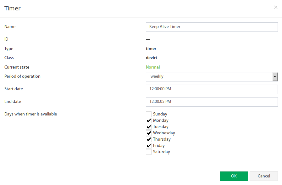
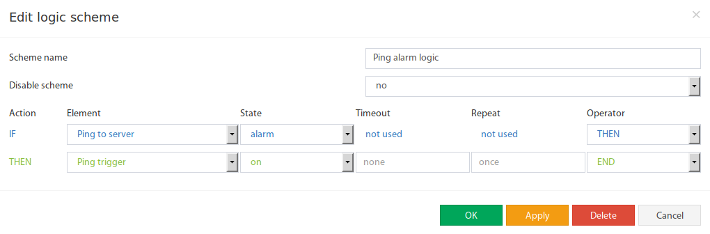
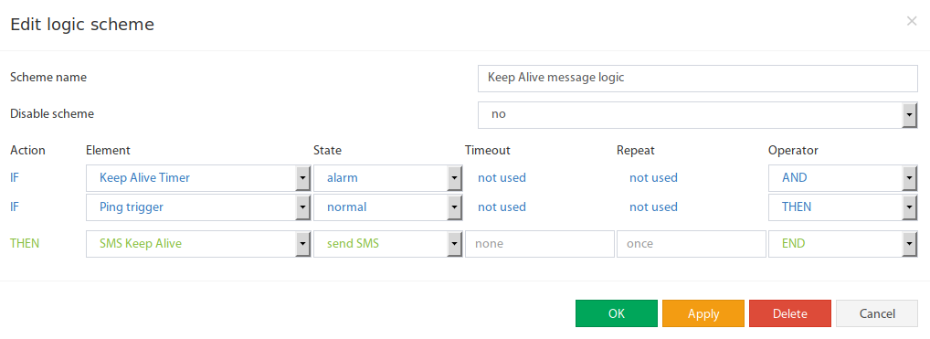
A weekly "Keep Alive" message should be sent Monday to Friday at 12:00 – but only if no ping failures have occurred.
- Create timer: Weekly, Mon–Fri, 12:00:00, duration 5 seconds (until 12:00:05).
- Create trigger that indicates the normal state of the ping.
- Logic scheme: Activate trigger when ping failure is detected.
- Logic scheme: Send Keep-Alive message when timer is active AND Trigger = Normal.
- Logic scheme: Deactivate trigger when the timer expires.
 🔍 Enlarge
 🔍 Enlarge
 🔍 Enlarge
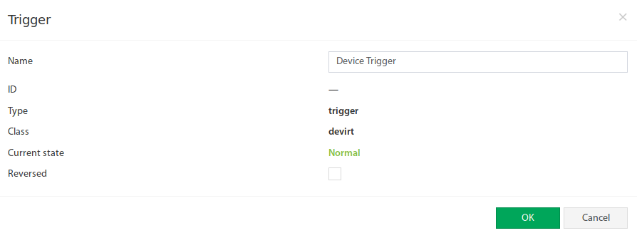
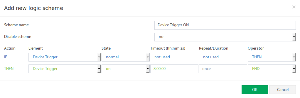
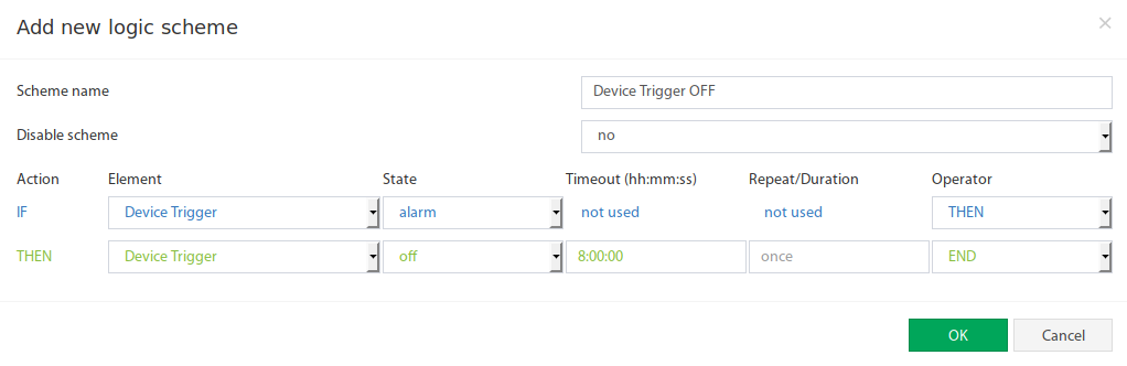
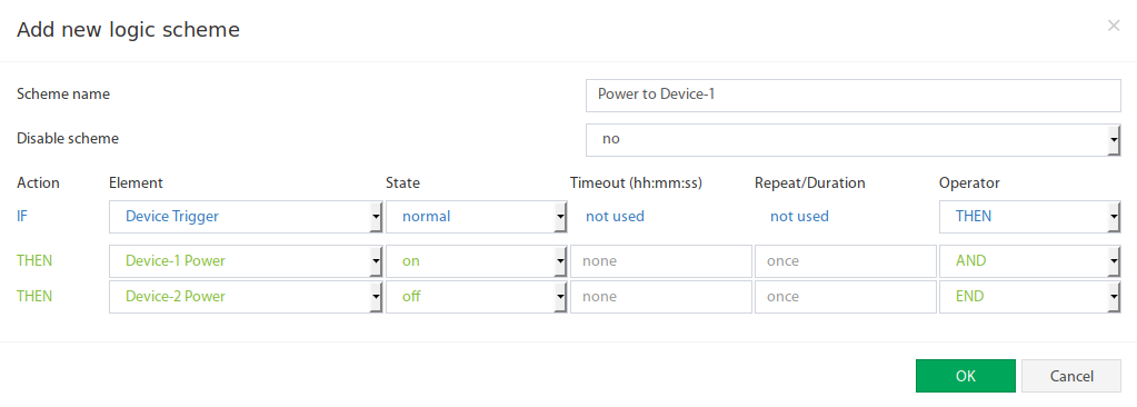
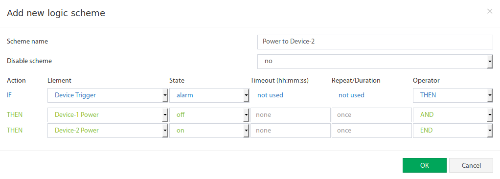
Two backup devices should operate in an 8-hour rotation – 8 hours Device A, then 8 hours Device B.
- Create a trigger that switches between Device A and Device B.
- Create two logic schemes to set the trigger to ON or OFF after 8 hours (28800 seconds).
- Create two more logic schemes for the actual device control (relay ON/OFF depending on trigger state).
 🔍 Enlarge
 🔍 Enlarge
 🔍 Enlarge
 🔍 Enlarge
 🔍 Enlarge