
Spider: Sensor hub for RS-485 and 1-Wire sensors


€200.20
Six 1-Wire probes on the RS-485 bus
The HW group Spider is a converter that connects up to 4 1-Wire probes (max. 6 values) or 4 dry contacts to the RS-485 bus. The Spider is designed for operation with the Poseidon 2250.
The Poseidon 2250 supports a total of up to 26 probes or 4 Spider units. From two connected Spider units onwards, an additional power supply is required. The RS-485 communication bus can be up to 1200 m (4000 ft) long; the last sensor at the end of the line must terminate the bus (“Bus Mode” jumper set to LAST).
4 1-Wire probes or dry contacts on the RS-485 bus
The Spider connects classic 1-Wire sensors to the RS-485 bus of the Poseidon 2250 and is particularly suitable for applications with complex cabling.
4x 1-Wire probe or dry contact
Four RJ11/RJ12 inputs for 1-Wire temperature or humidity probes from HW group (max. 6 values) or for 4 galvanically isolated dry contacts.
RS-485 output with power supply
Two RJ45 ports for the RS-485 bus including power supply enable the daisy-chaining of multiple Spider units.
DIP switches for address & bus mode
DIP switches are used to set the bus address, dry-contact detection and the position on the RS-485 bus (BRANCH, MIDDLE, LAST).
Flexible power supply
Powered via the RS-485 bus from the Poseidon or, when multiple Spider units are used, via an external 12V power supply through the barrel jack input.
LED status indication
Each input (I1 to I4) has its own LED that briefly flashes when the Poseidon reads the value via RS-485.
Fast pulse detection
Responds even to extremely short dry-contact pulses from 30 ms.
How the Spider is built
The compact plastic housing measures approximately 71 x 55 x 37 mm and weighs about 63 g. Operating conditions: -30°C to 70°C at 0–100 % relative humidity (storage: -30°C to 60°C, 5–95 % RH).
Compact plastic housing
Small housing suitable for industrial mounting along walls, 19" racks or behind cooling equipment.
4 inputs (RJ11/RJ12/RJ45)
Four connectors (numbered 1–4) for 1-Wire probes (temperature, humidity) from HW group or galvanically isolated dry contacts. If a dry contact is connected, DIP4 of the “BUS ADDRESS” switch must be set to “0”.
External power connector
Barrel jack input for connecting an external 12V DC power supply, which is required when daisy-chaining multiple Spider units.
2x RJ45 for RS-485 bus
Two RJ45 outputs transmit the RS-485 bus including 12V DC power supply and allow multiple Spiders to be daisy-chained or connected to an S-Hub.
DIP switches “BUS MODE” and “BUS ADDRESS”
The “BUS MODE” switch defines the Spider’s position on the RS-485 bus (BRANCH, MIDDLE or LAST). The “BUS ADDRESS” switch assigns the bus address (uppercase/lowercase letters) and determines whether dry contacts are detected.
Bus mode and bus address
The position of each Spider on the RS-485 bus is set via the “BUS MODE” DIP switch.
- BRANCH (0000): Intermediate point of a branch, both RJ45 sockets active
- MIDDLE (1100): Connected directly to an S-Hub, end of a branch, only one RJ45 socket used
- LAST (0011): Last unit on the bus, bus termination, only one RJ45 socket used
- BUS ADDRESS: 000x–111x assign the addresses A–F to U–Z or a–f to u–z; the last bit (xxx0/xxx1) enables or disables dry-contact detection
If a 1-Wire sensor is not found on an input at power-up, the Spider treats it either as a dry contact (DIP4=Off) or ignores the input (DIP4=On), depending on the DIP4 setting. After any change to the DIP switches or the connected probes, the Spider must be powered off and restarted so that it re-detects the sensors.
Protocol and integration with the Poseidon 2250
The probes operate in request-response mode with a maximum response time of 50 ms.
- Bus: RS-485, ASCII protocol, 9600 baud, 8 data bits, no parity, 1 stop bit
- Address range: “A” to “Z” (except “T”) as well as “a” to “z”
- Response time: max. 50 ms per command
- Direct connection to the Poseidon 2250, which recognises the Spider as a 1-Wire / dry-contact extension
Commissioning in a few steps
The Spider is configured directly via the connected Poseidon 2250 and does not require its own software.
- Place the Spider at the desired mounting location (e.g. along a 19" rack or behind cooling equipment)
- Connect 1-Wire probes or dry contacts to inputs 1–4; for dry contacts set DIP4 to “0”
- Set the bus mode (BRANCH, MIDDLE or LAST) and the bus address using the DIP switches
- Connect the Spider via RJ45 cable to the RS-485 bus of the Poseidon 2250 or to an S-Hub
- If two or more Spider units are used: connect an external 12V power supply
- Power-cycle the Spider so that the probes are detected
- Configure the probes on the Poseidon 2250
Why the Spider is the right choice
Flexible sensing
1-Wire probes or dry contacts on a single device.
Daisy-chainable
Multiple Spiders can be combined in BRANCH, MIDDLE or LAST mode.
Long bus range
RS-485 bus up to 1200 m in length.
Fast response
Detects dry-contact pulses from 30 ms.
Simple configuration
Address and bus mode via DIP switches, without software.
24-month warranty
According to the manufacturer with 24 months warranty from the date of purchase.
Practical application example
The Spider is particularly suitable for complex cabling scenarios in server rooms and industrial buildings.
Practical example: In a supermarket, an RS-485 bus is run along the freezer cabinets. Several Spider units in MIDDLE or BRANCH mode each connect 1-Wire temperature and humidity probes as well as door contacts to the central Poseidon 2250. The last Spider at the end of the line is operated in LAST mode and terminates the bus, so that all measured values reliably reach the Poseidon.
Frequently asked questions
What is the HW group Spider and what is it used for?
The Spider is a converter that connects up to 4 1-Wire probes or 4 dry contacts to the RS-485 bus of a Poseidon 2250. It is particularly suitable for applications with complex cabling in server rooms and industrial buildings.
Does the Spider have different variants?
No, the Spider is supplied as a standalone device without options.
How many Spiders can be connected to one Poseidon 2250?
The Poseidon 2250 supports a total of up to 26 probes or a maximum of 4 Spider units. From two Spider units onwards, an additional external power supply is required.
What do the bus modes BRANCH, MIDDLE and LAST mean?
The bus mode defines the Spider’s position on the RS-485 bus: BRANCH for an intermediate point within a branch, MIDDLE for direct connection to an S-Hub or the end of a branch, and LAST for the last unit on the bus that terminates it.
Can 1-Wire probes and dry contacts be connected at the same time?
Yes. Each of the four inputs can accept either a 1-Wire probe or a dry contact. If a dry contact is connected, DIP4 of the “BUS ADDRESS” switch must be set to “0”.
How is the Spider powered?
The Spider draws its 12V power supply via the RS-485 bus from the Poseidon. When multiple Spider units are daisy-chained, an additional external 12V DC power supply via the barrel jack input is required from the second unit onwards.
Questions about the Spider?
Our support team in Germany will advise you free of charge on selection, sensors and configuration.
- Inputs: 4x RJ11 for dry contacts (NO/NC) or 1-Wire sensors (e.g., Temp-1Wire, Hum-1Wire)
- Interface: RS-485 bus (2x RJ45 for daisy-chain), max. cable length 1200 m
- Power supply: Via RS-485 bus from the Poseidon unit or external 12V power supply (barrel connector, required when using more than one Spider unit)
- Configuration: DIP switch for RS-485 address (sensor ID)
- Response time: Detection of dry contact pulses from 30 ms
Installation:
- Connect the Spider to the Poseidon unit via RJ45 cable
- Connect up to four dry contacts or 1-Wire sensors to the RJ11 ports
- Jumper setting: Last Spider on the RS-485 bus set to "LAST", all others set to "MIDDLE"
- External 12V power supply (e.g., HWg-600528) required when using more than one Spider unit
- Configure the sensors via the web interface of the Poseidon unit or HWg-PDMS software
Safety instructions:
- Installation only by qualified personnel
- Use a suitable 12V power supply that complies with local electrical regulations
- Do not install in environments with explosive gases or vapors
- Complies with EU regulations and industry standards
Further monitoring devices


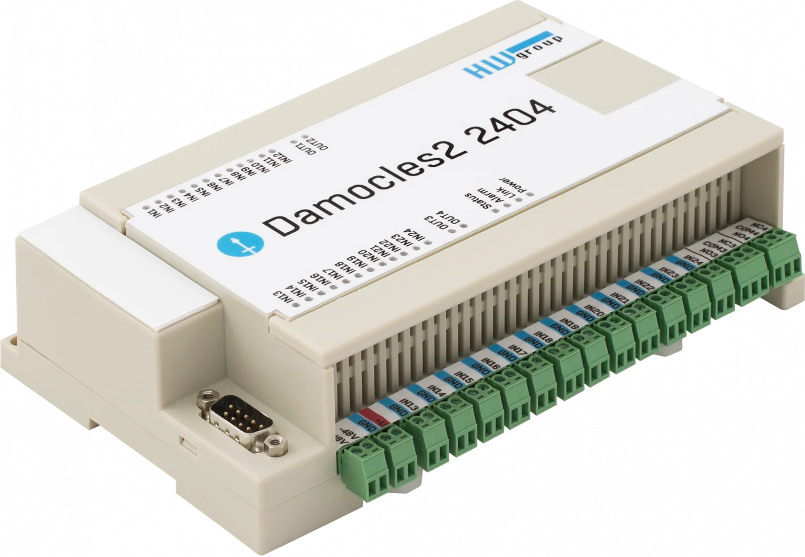


Available sensors


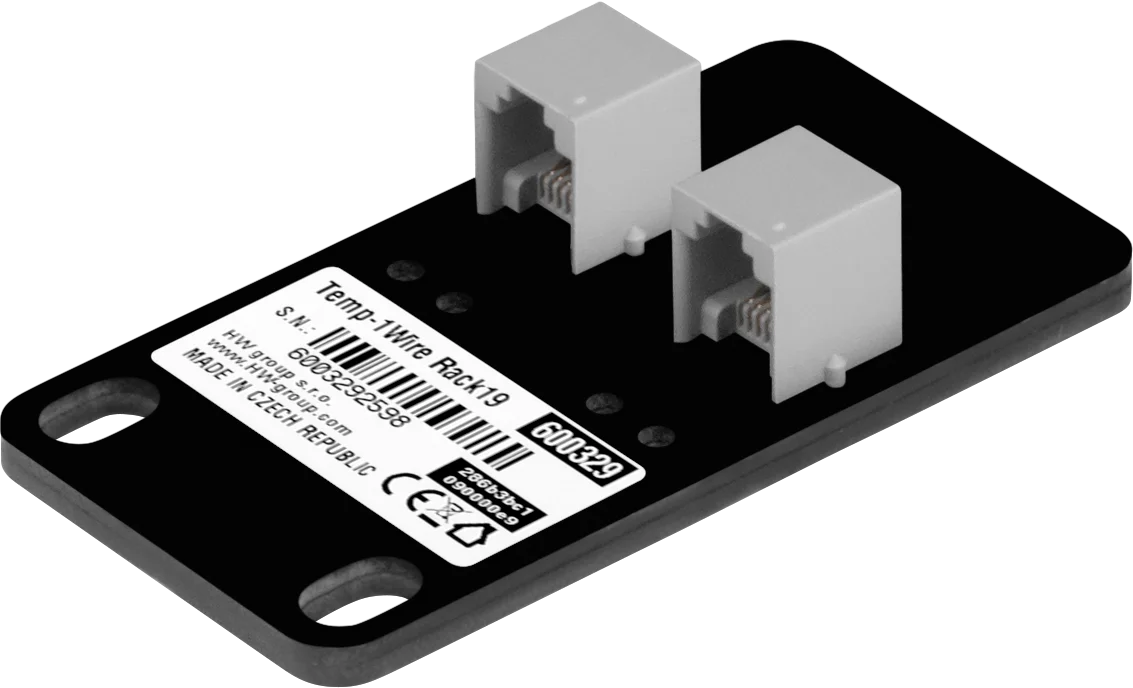


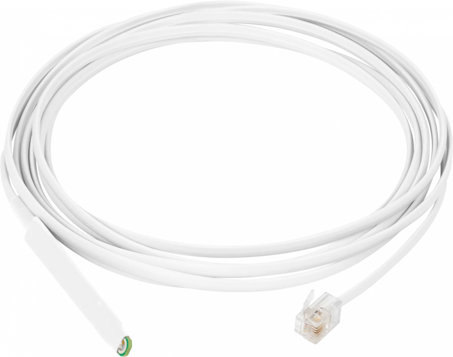


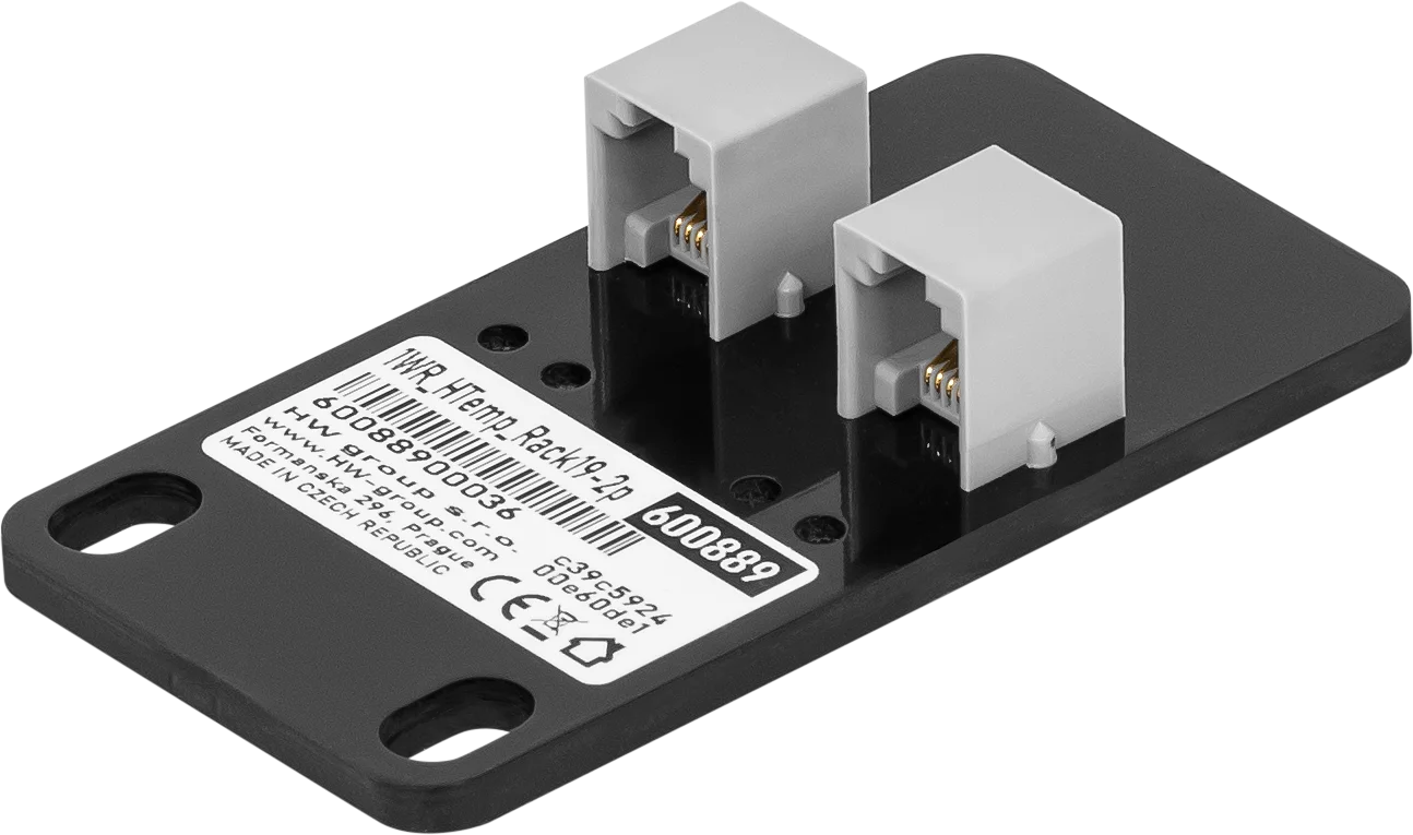







Accessories

Mounting Plate D Bracket for Ares and Poseidon2 Operating environment: -3°C - 85°C / 0%RH - 100%RH Storage environment: -30°C - 60°C / 5%RH - 95%RH Dimensions: 74 x 6 x 120 (W x H x D) / 58g Warranty: 24 months Wall mounting plate for Ares, Poseidon2 3266/68 and other products.

DB9 LapLink Cable 2m A LapLink cable (also known as Lablink or null-printer cable) is a cable used to connect two computers directly via a cable connection. Housing: Plastic Type: Cable

DIN-Rail Box Set A mounting kit for installing HW-group devices on a DIN rail. Applications and Use: Mounting kit for installing HW-group devices with metal housing on a DIN rail. Operating environment: -30°C - 85°C / 0%RH - 100%RH Storage environment: -30°C - 60°C / 5%RH - 95%RH Dimensions: 45 x 11 x 105 (W x H x D) / 22g
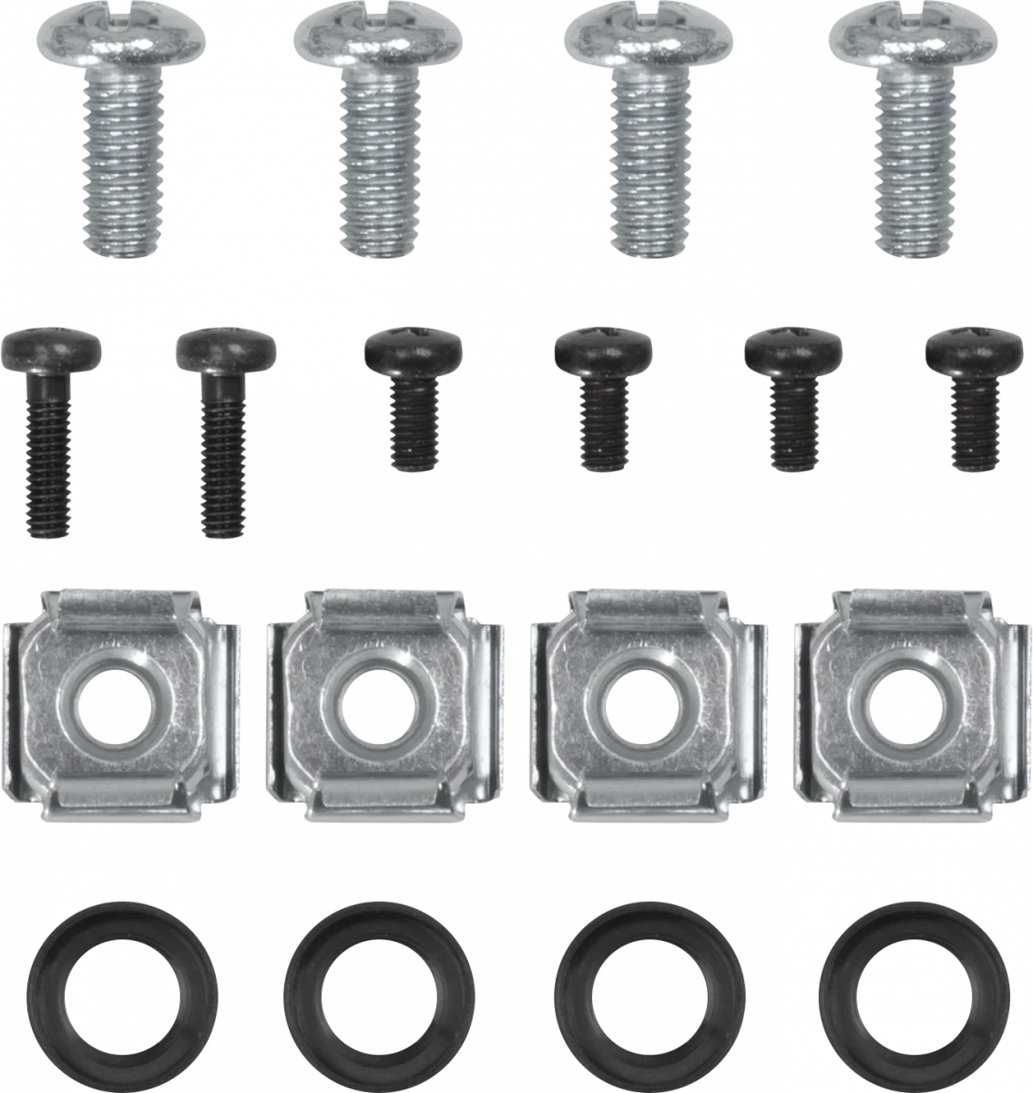
Mounting Kit Screw set for mechanical mounting Applications and Use: Screw set for mechanical fastening


Mounting Plate E- 1U Rack (cabinet) mounting plate, 1U mounting for HW-group Ares and Poseidon2 devices Operating environment: -30°C - 85°C / 0%RH - 100%RH Storage environment: -30°C - 60°C / 5%RH - 95%RH Dimensions: 127 x 45 x 94 (W x H x D) / 137g Warranty: 24 months Rack (cabinet) mounting plate, 1U mounting for HW-group Ares, Poseidon2 3266/3268 and other products.

Mounting Plate L DIN Rail DIN rail mounting plate for Ares, Poseidon2 3268, and other products. Features: Metal housing Wall mounting Applications and Use: Profiles for metal-encapsulated HWg devices for wall mounting. Dimensions: 150 x 120 x 45 (W x H x D) / 65g Warranty: 24 months


Mounting Kit for Poseidon2 4002 and HWg-SMS-GW3 Applications and Use: Mounting kit for Poseidon2 4002 and HWg-SMS-GW3 Operating environment: -30°C - 85°C / 0%RH - 100%RH Storage environment: -30°C - 60°C / 5%RH - 95%RH Dimensions: 136 x 45 x 16 (W x H x D) / 165g Warranty: 24 months


Rack Shelf 1U A versatile solution for easy mounting of HW-group devices in 1U racks. Operating environment: -30°C - 85°C / 0%RH - 100%RH Storage environment: -30°C - 60°C / 5%RH - 95%RH Dimensions: 485 x 44 x 104 (W x H x D) / 597g Warranty: 24 months Housing: Metal Type: Wall mounting This shelf makes it easy to use devices in racks. You can even combine different 1U products and sensors.

Software


Manufacturer information:
HW group s. r. o.
Rumunská 26
Prague, 120 00
Czech Republic
Phone: +420 222 511 918
Email: sales@hwg.cz
Responsible person:
Didactum® Security GmbH
Im Mühlenfeld 4
48163 Münster
Deutschland
Fon:
(+49) 250 19 71 63 54 / (+49) 171 33 11 577
Email: info@didactum-security.de
