
Meter 1f PRO1-Mb: Precise energy meter


€172.00
The MID-certified DIN rail energy meter with M-Bus
The HW group Meter 1f PRO1-Mb is a single-phase energy meter for DIN rail mounting with an integrated M-Bus interface. It records a wide range of electrical instantaneous values such as voltage, current, active, reactive and apparent power, frequency and power factor, displaying them both on the LCD screen and via M-Bus. Thanks to accuracy class 1/B according to the Measuring Instruments Directive 2014/32/EU (MID), the meter is also approved for billing purposes.
The standardized M-Bus interface (EN 13757-3) allows consumption data to be read remotely with ease, making the meter ideal for building management systems. Additionally, an optically isolated S0 pulse output is available, enabling consumption to be counted independently of the M-Bus.
The Meter 1f PRO1-Mb is offered in two load variants, which differ in maximum current, operating temperature range and housing width.
Precise energy measurement according to MID
The meter records a wide range of electrical parameters with high accuracy.
Accuracy class B (1 %)
MID-certified according to 2014/32/EU and EN50470-1/3, suitable for billing purposes.
Comprehensive instantaneous values
Voltage, current, active, reactive and apparent power, frequency and power factor, each for forward and reverse direction.
Rated voltage 230 V AC
Operating voltage range 195–253 V AC at 50 Hz ±10 %, basic current (Ib) 5 A.
Low basic errors
±1.5 % at 0.05Ib or ±1.0 % in the range 0.1Ib to Imax, depending on power factor.
Long-term data storage
Stored values remain preserved for more than 10 years even without power supply.
How the Meter 1f PRO1-Mb is constructed
The flame-retardant PC plastic housing is designed for mounting on a 35 mm DIN rail and consolidates all connections on the underside.
Plastic housing, protection class II
Flame-retardant PC housing with IP51 protection against dust and water, insulated and encapsulated according to protection class II.
Mains connection terminals
Terminal 1 (L-IN, phase input), terminal 3 (L-OUT, phase output), terminal 4 (N input) and terminal 6 (N output) for connection to the 230 V mains.
S0 pulse output
Terminals 20 and 21 provide an optically isolated, polarity-dependent open-collector pulse output that requires an external voltage source of 5–27 V DC at max. 100 mA switching current.
M-Bus connection
Terminals 23 and 24 serve as the M-Bus communication contact on the PRO1-Mb for remote reading of measured values.
6-digit LCD display
The top line shows energy direction (forward/reverse) and communication activity via dot indicators, while the bottom line displays the actual measured values. Energy values are shown up to 9999.99 kWh and then switch to 99999.9 kWh.
Control button
A single button on the device front is used to scroll through display pages and – depending on how long it is held – to access and confirm programming modes.
Infrared interface
An infrared interface (900–1000 nm, protocol IEC62056-21:2002) enables reading and configuring the meter via a contact infrared head and PC software.
Red status LED
The red LED on the front flashes proportionally to energy flow – 10,000 times per kWh – thus directly indicating current consumption.
Available for 45 A or 100 A
The Meter 1f PRO1-Mb is available in two load variants, which differ in maximum operating current, operating temperature range and housing width.
Please note: The desired variant must be selected above the shopping cart button. Choose the variant that matches the maximum expected current of your system.
Variant 1 – 45 A
1-phase 230 V M-Bus energy meter with maximum load of 45 A and M-Bus data output. Operating temperature -25 °C to +55 °C.
Variant 2 – 100 A
1-phase 230 V M-Bus energy meter with maximum load of 100 A and M-Bus data output. According to the manufacturer, designed for a wider operating temperature range down to -40 °C.
Display and navigation via a single button
All measured values and settings can be accessed via a single button on the device.
- Automatic scrolling through display pages, factory setting every 10 seconds (adjustable from 1 to 30 seconds)
- Short button press (under 3 seconds) manually scrolls through display pages
- After 30 seconds without operation, the display automatically returns to auto-scroll mode
- Individual registers can be added to or removed from automatic scrolling by holding the button for 5 seconds
- Blue backlight optionally always on, off, or only on button press
- Resettable daily counter for forward consumption that can be reset to 0 at any time
Three programming levels for different settings
The meter distinguishes between a pure read level and two write levels, one of which is additionally password-protected.
- Programming mode 1 (read only): Program checksum and serial number
- Programming mode 2 (write): LCD cycle time, backlight, Modbus/M-Bus ID, resettable kWh
- Programming mode 3 (write, password-protected): S0 output rate, combination code, baud rate, parity, power-down counter, password
- The standard password for programming mode 3 is 0000 and can be changed at any time
- Each new setting is confirmed by holding the button for 3 seconds; the display then shows "OK"
Flexible adaptation to downstream systems
Both the pulse output and the type of total energy calculation can be individually configured.
- S0 output rate selectable: 10,000 / 2,000 / 1,000 / 100 / 10 / 1 / 0.1 / 0.01 pulses per kWh
- Pulse width 32 ms at powers up to 5,625 W, 11.2 ms above that
- Combination code C-01: forward energy only
- Combination code C-04: reverse energy only
- Combination code C-05: forward plus reverse energy
- Combination code C-06: reverse minus forward energy
- Combination code C-09 / C-10: forward minus reverse energy
Remote reading according to EN13757-3
Meter readings can be read in a structured and standardized way via the M-Bus.
- Baud rate selectable between 300, 600, 1200, 2400 (default), 4800 and 9600 baud
- Range up to 1000 m, up to 64 meters on one bus (depending on converter, baud rate and installation conditions)
- Downlink signal (master to slave) via voltage modulation, uplink signal (slave to master) via current modulation
- Cable type JYSTY (n×2×0.8), protocol EN13757-3
- M-Bus ID adjustable from 000 to 250, factory setting 000
- Secondary address is factory-set to the last 8 digits of the serial number, but can be changed via infrared or M-Bus
- Data blocks include total, forward and reverse active energy as well as tariff-separated values T1/T2
- Detailed technical information on the M-Bus standard at www.m-bus.com
Convenient reading and programming via PC
All PRO1 meters can be read and configured either via an infrared interface with a PC.
- IR standard IRDA according to IEC62056-21:2002 (IEC1107)
- Infrared converter and associated software are available separately
- The software allows reading individual or multiple registers as well as setting new values directly on the PC
- Changes can be prepared in so-called "Save mode" and then transferred collectively to the meter
Professional installation on the DIN rail
- Mounting on a 35 mm DIN rail, exclusively for indoor use or in a suitable IP-classified control cabinet
- Installation only by qualified personnel, with insulated tools and de-energized circuit
- Fuse, thermal protection switch or circuit breaker on the phase line, not on the neutral conductor
- The meter must be installed on a fire-resistant wall, well ventilated and dry
- In case of dust exposure, an additional protective box should be provided
- In case of frequent overvoltages, such as from thunderstorms or welding equipment, the use of a surge protection device is recommended
- After installation, the meter should be sealed to prevent tampering; a broken seal voids the warranty
Common problems and solutions
- Red consumption LED does not flash: no or very low load connected – check load, measure with an ohmmeter if necessary
- Meter reading does not increase: almost no load connected – check LED flashing
- No pulse output: external voltage source (5–27 V DC) missing or wiring reversed – check connection to pin 20 (+) and pin 21 (–)
- Incorrect pulse output rate: set correctly via infrared software or programming mode 3
- Error code Err 01: EEPROM error – request meter replacement via support
- Error code Err 02: checksum error in program code – request meter replacement via support
Application areas
- Building management: record and optimize energy consumption in office buildings or residential complexes
- Data centers: monitor power consumption of servers and UPS systems
- Industrial applications: precise monitoring of machines and production systems
- Billing systems: MID-certified recording of consumption data for utility cost accounting
- Energy management: combination of consumption data with other measured variables such as temperature or humidity
The HW group Meter 1f PRO1-Mb combines MID-certified, high-precision energy measurement with robust M-Bus connectivity and an additional S0 pulse output – a practical solution for submetering, building management and energy monitoring in commercial, data center and industrial applications.
Frequently asked questions
What is the Meter 1f PRO1-Mb and what is it used for?
The Meter 1f PRO1-Mb is a MID-certified, single-phase energy meter for DIN rail mounting with M-Bus interface. It is used for submetering, building management and energy monitoring in offices, data centers and industrial facilities.
What is the difference between the 45 A and 100 A variants?
Both variants are 1-phase 230 V M-Bus energy meters, but differ in maximum permissible current load (45 A or 100 A). According to the manufacturer, the 100 A variant is additionally designed for a wider operating temperature range.
Is the meter suitable for billing purposes?
Yes. The Meter 1f PRO1-Mb is certified according to the Measuring Instruments Directive 2014/32/EU (MID) and meets accuracy class B (1 %) according to EN50470-1/3.
Can the S0 pulse output be individually configured?
Yes. The pulse rate can be set in password-protected programming mode 3 to one of eight values between 10,000 and 0.01 pulses per kWh.
How is the meter configured?
Either directly via the control button and LCD display in three programming modes, or conveniently via the infrared interface with a separately available IR converter and PC software.
What happens if the meter seal is broken?
According to the manufacturer, the meter must never be opened. A broken seal may impair the function or accuracy of the device and voids all warranty claims.
What do error codes Err 01 and Err 02 mean?
Err 01 indicates an EEPROM error, Err 02 a checksum error in the program code. In both cases, the meter must be replaced; please contact our support.
Note on sources: HW group technically lists the 100 A version as a separate "PRO2" series with its own manual, different temperature specifications (-40 °C to +80 °C) and a wider, two-part housing (36 instead of 18 mm). The user manual uploaded here covers exclusively the PRO1 series (including the 45 A version); all operating, programming and M-Bus information in this article comes from this PRO1 manual and applies largely identically to both variants, but may differ in details for the 100 A version.
Questions about the Meter 1f PRO1-Mb?
Our support team in Germany will advise you free of charge on selection, installation and configuration.
- Option 1:
1 Phase 230V M-Bus Energy Meter, max. load 45A. M-Bus data output - Option 2:
1 Phase 230V M-Bus Energy Meter, max. 100A. M-Bus data output
Electrical Specifications:
- Housing: PC flame-retardant plastic
- Nominal voltage (Un): 230V AC
- Operating voltage: 195-253V AC
- Basic current (Ib): 5A
- Maximum rated current (Imax): 45A
- Operating current range: 0.4%Ib-Imax
- Overcurrent withstand: 30Imax for 0.01s
- Operating frequency range: 50Hz ±10%
- Internal power consumption: ≤2W/phase - ≤10VA/phase
Insulation Capabilities:
- AC voltage test: 4KV for 1 minute
- Impulse voltage test: 6KV – 1.2μS waveform
- Protection class: II (insulated encapsulated meter)
- Protection degree: IP51 (protection against dust and water)
Performance Criteria:
- Operating humidity: ≤ 75%
- Storage humidity: ≤ 95%
- Operating temperature: -25°C to +55°C
- Storage temperature: -30°C to +70°C
- International standard: EN50470-1/3
- Accuracy class: B (=1% accuracy)
Basic Error:
- 0.05Ib Cosφ = 1: ±1.5%
- 0.1Ib Cosφ = 0.5L: ±1.5%
- Cosφ = 0.8C: ±1.5%
- 0.1Ib - Imax Cosφ = 1: ±1.0%
- 0.2Ib - Imax Cosφ = 0.5L: ±1.0%
- Cosφ = 0.8C: ±1.0%
Outputs and Communication:
- Test output flash rate (red LED): 10,000 imp/kWh
- Pulse output rate: 10,000/2,000/1,000/100/10/1/0.1/0.01 imp/kWh
- Pulse width: ≤ 5625W = 32ms, > 5625W = 11.2ms
- S0 output: Optically isolated, open collector transistor
- External voltage: 5-27V DC, max. switching current: 100mA
Infrared Specification:
- Infrared wavelength: 900-1000nm
- Communication distance: Direct contact
- Protocol: IEC62056-21:2002 (IEC1107)
M-Bus Communication (PRO1-Mb only):
- Bus type: M-Bus
- Baud rate: 300, 600, 1200, 2400 (default), 4800 and 9600
- Range: ≤1000m
- Downlink signal: Master to slave, voltage modulation
- Uplink signal: Slave to master, current modulation
- Cable: JYSTY (nx2x0.8)
- Protocol: EN13757-3
- Unit loads: ± 2
- Max. number of meters: 64
RS485 Communication (PRO1-Mod only):
- Bus type: RS485
- Protocol: MODBUS RTU with 16-bit CRC
- Baud rate: 1200, 2400, 4800 and 9600 (default)
- Address range: 1-247 user-defined
- Maximum bus load: 60 meters per bus
- Range: 1000m
Dimensions:
- Height without protective cover: 90 mm
- Height: 117 mm
- Width: 17.5 mm
- Depth: 63 mm
- Max. diameter of current connection terminals: 8 mm² (solid copper)
- Weight: 0.08 kg (net)
Data Storage and Display:
- Data storage: Data can be stored for more than 10 years without power
- LCD display: 6-digit with blue backlight
- Display range: 9999.99 kWh to 99999.9 kWh
- Automatic scrolling: every 10 seconds (adjustable 1-30 seconds)
Installation Requirements:
- Mechanical environment: 'M1' (low shocks and vibrations)
- Electromagnetic environment: 'E2' (according to 2014/32/EU directive)
- Usage: Indoor use only
- Mounting: 35mm DIN rail
- Installation: In suitable IP-rated enclosure
Monitoring devices


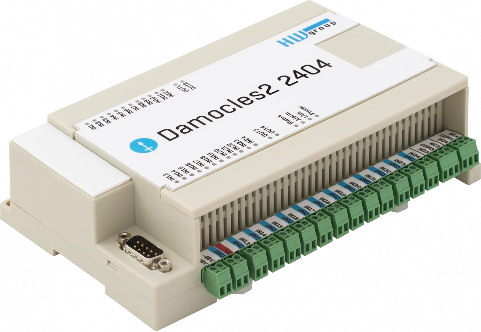


Other available sensors


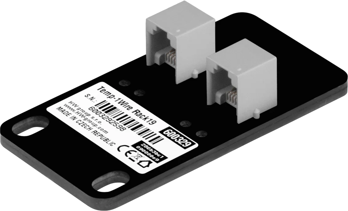


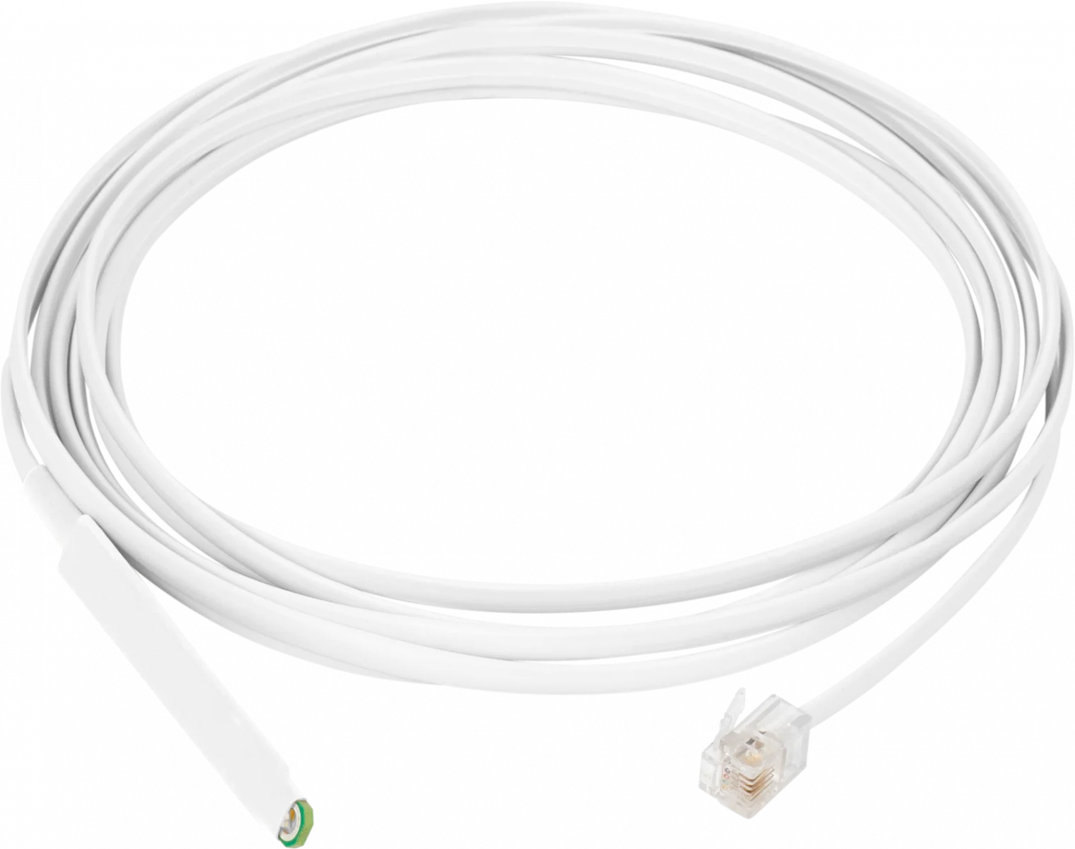


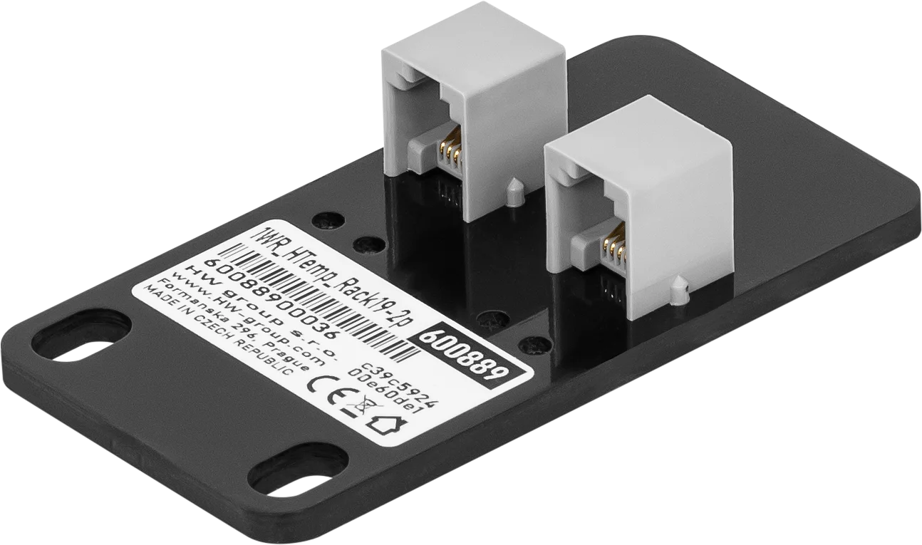







Extension units


Accessories

Mounting Plate D Bracket for Ares and Poseidon2 Operating environment: -3°C - 85°C / 0%RH - 100%RH Storage environment: -30°C - 60°C / 5%RH - 95%RH Dimensions: 74 x 6 x 120 (W x H x D) / 58g Warranty: 24 months Wall mounting plate for Ares, Poseidon2 3266/68 and other products.

DB9 LapLink Cable 2m A LapLink cable (also known as Lablink or null-printer cable) is a cable used to connect two computers directly via a cable connection. Housing: Plastic Type: Cable

DIN-Rail Box Set A mounting kit for installing HW-group devices on a DIN rail. Applications and Use: Mounting kit for installing HW-group devices with metal housing on a DIN rail. Operating environment: -30°C - 85°C / 0%RH - 100%RH Storage environment: -30°C - 60°C / 5%RH - 95%RH Dimensions: 45 x 11 x 105 (W x H x D) / 22g
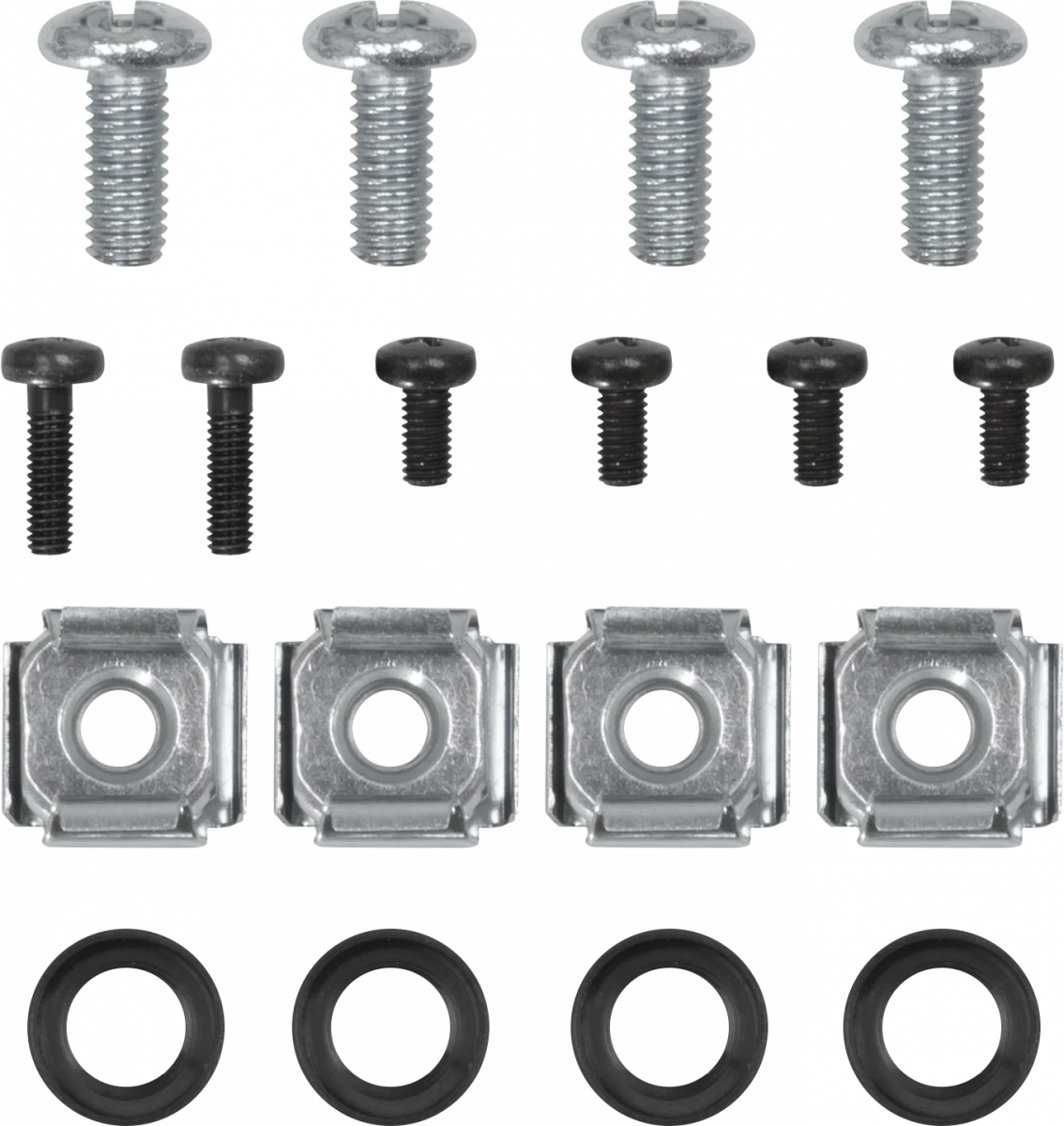
Mounting Kit Screw set for mechanical mounting Applications and Use: Screw set for mechanical fastening


Mounting Plate E- 1U Rack (cabinet) mounting plate, 1U mounting for HW-group Ares and Poseidon2 devices Operating environment: -30°C - 85°C / 0%RH - 100%RH Storage environment: -30°C - 60°C / 5%RH - 95%RH Dimensions: 127 x 45 x 94 (W x H x D) / 137g Warranty: 24 months Rack (cabinet) mounting plate, 1U mounting for HW-group Ares, Poseidon2 3266/3268 and other products.

Mounting Plate L DIN Rail DIN rail mounting plate for Ares, Poseidon2 3268, and other products. Features: Metal housing Wall mounting Applications and Use: Profiles for metal-encapsulated HWg devices for wall mounting. Dimensions: 150 x 120 x 45 (W x H x D) / 65g Warranty: 24 months


Mounting Kit for Poseidon2 4002 and HWg-SMS-GW3 Applications and Use: Mounting kit for Poseidon2 4002 and HWg-SMS-GW3 Operating environment: -30°C - 85°C / 0%RH - 100%RH Storage environment: -30°C - 60°C / 5%RH - 95%RH Dimensions: 136 x 45 x 16 (W x H x D) / 165g Warranty: 24 months


Rack Shelf 1U A versatile solution for easy mounting of HW-group devices in 1U racks. Operating environment: -30°C - 85°C / 0%RH - 100%RH Storage environment: -30°C - 60°C / 5%RH - 95%RH Dimensions: 485 x 44 x 104 (W x H x D) / 597g Warranty: 24 months Housing: Metal Type: Wall mounting This shelf makes it easy to use devices in racks. You can even combine different 1U products and sensors.
Software


Manufacturer information:
HW group s. r. o.
Rumunská 26
Prague, 120 00
Czech Republic
Phone: +420 222 511 918
Email: sales@hwg.cz
Responsible person:
Didactum® Security GmbH
Im Mühlenfeld 4
48163 Münster
Deutschland
Fon:
(+49) 250 19 71 63 54 / (+49) 171 33 11 577
Email: info@didactum-security.de
